


 Chinese
 Spanish
 French
 Russian
 German
 Portuguese
 Indonesian
 Thai
Thai Vietnamese
 Arabic

A water quality sensor data contract defines exactly how a field measurement becomes a trusted PLC, SCADA or IoT value. Before procurement, the project team should agree on device address, serial settings, register, data type, byte order, scale, unit, status handling, alarm behavior and acceptance evidence—not merely ask whether the sensor “supports Modbus.”

Why a Modbus-Compatible Sensor Can Still Fail Integration
RS485 describes the electrical layer, while Modbus RTU defines the message protocol. Neither statement tells a controls engineer which register contains the process value or how two register words must be interpreted. A sensor and PLC may communicate successfully while displaying a value that is multiplied by ten, assigned the wrong unit or assembled in the wrong word order.
Use the Modbus Organization specifications and implementation guides as the protocol authority, and use the manual and register map delivered for the exact sensor model as the device authority. The protocol specification defines transaction behavior and function codes; it does not replace the manufacturer’s register addresses, data types, scaling or writable-command limits.
The commercial risk is wider than a programming delay. A wrong pH, dissolved oxygen, conductivity or turbidity value can change dosing, aeration, diversion or discharge decisions. If the historian stores the error without a quality flag, the same data may later be used in compliance reports, service investigations or performance guarantees. Correcting the PLC tag does not repair the historical record.
One page in a quotation should therefore identify the complete digital interface. This is especially important for distributors supplying different PLC brands, OEM skid builders repeating one design across projects, and EPC teams dividing responsibility among the sensor supplier, panel builder and SCADA contractor.
What the Water Quality Sensor Data Contract Must Contain
| Contract field | Required definition | Project risk controlled |
|---|---|---|
| Device identity | Manufacturer, exact model, serial number and ordered measurement module | Prevents a register map or range from another model being copied into the PLC |
| Physical and protocol layer | RS485 two-wire arrangement, Modbus RTU, baud rate, parity, data bits and stop bits | Prevents silent devices and mismatched serial frames |
| Network identity | Unique slave address and approved address schedule | Prevents multidrop collisions and commissioning rework |
| Process value | Function code, register, data type, word order, scale and engineering unit | Prevents believable but numerically incorrect readings |
| Status | Communication state, device fault, cleaning, calibration and maintenance state | Stops invalid measurements from being treated as process events |
| Timing | Polling interval, response timeout, retry count and stale-data limit | Separates a process change from delayed or frozen data |
| Write control | Approved writable registers, authority and change record | Protects address, calibration and configuration from unintended commands |
| Acceptance evidence | Test values, reference comparison, raw frame or register record and signed result | Creates traceable handover evidence for the full signal path |
Engineering boundary: do not infer a register address, data type or command from another YexSensor model. The quotation and delivered manual for the exact model must control the PLC program. A configurable range or optional output should also be written into the order rather than assumed from a product-family description.
Verified YexSensor Integration Reference
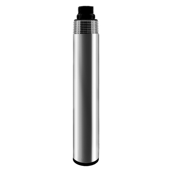
The YEX-S2-MPS-A online multi-parameter platform illustrates why model-specific configuration belongs in the interface schedule. It can carry up to eight parameters including temperature, with optional dissolved oxygen, optical COD, pH, ORP, conductivity or salinity, ammonium nitrogen and turbidity modules. The host should not create eight active tags unless those modules are included in the approved order.
| Selection item | Verified YEX-S2-MPS-A value | Corresponding procurement check |
|---|---|---|
| Measurement capacity | Up to eight parameters including temperature | List every ordered parameter, range, unit and calibration method individually |
| Field interface | RS485 Modbus RTU | Request the delivered register map and its revision with the shipment |
| Default serial format | 9600 bps, no parity, 8 data bits, 1 stop bit | Record any approved change in both the PLC backup and commissioning report |
| Device address | Default 6; configurable from 1 to 255 | Assign unique addresses before devices are connected to the common bus |
| Power supply | 12 VDC ±5% | Verify voltage at the installed device under load, including cable drop |
| Automatic cleaning | 6–6000 minute interval; 0–10 rotations; default 30 minutes and 3 rotations | Define cleaning status handling and adjust the cycle from actual fouling evidence |
These values define an integration starting point, not a universal template for all water quality probes. Measurement range, accuracy, wetted materials, cable, temperature and pressure limits remain specific to the ordered module. For a multi-parameter assembly, the approved datasheet package should preserve those specifications module by module.
Map the Complete Sensor-to-SCADA Signal Chain
This architecture keeps field communication separate from remote backhaul. An online sensor normally does not transmit directly to a cloud database just because a cellular dashboard is part of the project. The RTU or gateway polls the Modbus device, timestamps and validates the result, then publishes selected tags through the project’s upstream protocol.
Responsibility should be assigned at every boundary. The sensor supplier confirms the device interface and register map. The panel or controls contractor manages power, termination, addressing and PLC conversion. The SCADA contractor manages tag names, units, quality, timestamps, alarms and historian behavior. The network provider manages the backhaul. Without this division, each party may prove its own component while no one proves the end-to-end value.
Tag Naming and Engineering Units
Use tag names that identify site, process area, measurement point and parameter. Keep the displayed unit with the tag definition rather than in operator memory. Conductivity is a common source of error because µS/cm and mS/cm differ by a factor of 1,000. Concentration values may also be confused when mg/L and µg/L are copied between instruments, laboratory reports and dashboards.
Quality Flags and Stale Data
A retained last value can look stable after communication has failed. The SCADA point should therefore include a time-based stale state in addition to a numerical value. Cleaning, calibration and planned maintenance should suppress or qualify process alarms for a defined period, but they should not erase the underlying event. A zero should be stored as zero only when the device has returned a valid zero.
FAT and SAT Tests for the Digital Interface
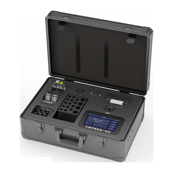
Factory acceptance testing should use the project PLC, RTU or an agreed simulator whenever practical. Record the device address, serial format and register map revision. Force or observe at least three stable values across the useful operating span, then compare the local or reference value with the raw register and engineering tag. Test loss of power, disconnected communication, retry behavior and recovery.
Site acceptance testing adds installation and process conditions. Confirm polarity, shielding, grounding, termination, cable routing, surge protection and voltage at the sensor. Compare a representative field sample or reference instrument according to the approved method. Trigger cleaning or maintenance status, confirm alarm delay and hysteresis, and verify that a stale value does not operate dosing equipment or a diversion valve.
The signed test sheet should identify the exact sensor, host program version, tag, unit, acceptance criterion, test result and responsible parties. A screenshot alone is weak evidence because it does not establish which register, scale or quality state produced the displayed number.
Application Scenarios and System Decisions
Wastewater Neutralization and Discharge Monitoring
Field challenge: pH can change quickly during batch discharge, while fouling and electrical noise can make the signal unstable. Integration solution: keep the raw pH, temperature, communication quality and maintenance status separate; apply dosing permissives and alarm persistence in the PLC. User value: operators can distinguish a real chemical excursion from a failed or serviced measurement before changing reagent feed.
Aquaculture and Recirculating Water Systems
Field challenge: dissolved oxygen alarms require timely response, but a frozen value can be more dangerous than an obvious fault. Integration solution: define polling, stale-data time, low-DO alarm delay and safe response to communication loss. User value: the system preserves actionable aeration logic without representing an old value as current pond or tank conditions.
Industrial Water Reuse
Field challenge: conductivity, turbidity and pH may be measured at different hydraulic points and cannot share one location merely for wiring convenience. Integration solution: assign each tag to a documented sample point, range and decision, then connect devices through an address schedule. User value: diversion and reuse decisions refer to the water actually entering the next process rather than to an ambiguous cabinet channel.
Remote River or Reservoir Stations
Field challenge: intermittent backhaul can interrupt dashboard updates even while the field sensor continues operating. Integration solution: let the data logger poll and timestamp local Modbus values, buffer records during a network outage and upload them with original timestamps after recovery. User value: network availability is no longer confused with water-quality availability, and data gaps can be investigated by layer.
Modbus, 4–20 mA and Sensor Architecture Selection
| Solution | Suitable project condition | Tradeoff and procurement check |
|---|---|---|
| RS485 Modbus RTU | Several values, status data or multiple addressed devices must reach a PLC, RTU or gateway | Approve the exact register map, serial settings, scaling, write permissions, bus design and failure logic |
| 4–20 mA | An existing panel needs one process value through a dedicated analog input | Confirm scaling, isolation, loop power and fault-current behavior; status and secondary values may need separate signals |
| Integrated multi-parameter sonde | Selected parameters share one representative point, service route and cleaning strategy | Freeze the delivered module list; one shared assembly can create a common maintenance or failure boundary |
| Separate parameter probes | Measurements belong at different process locations or require independent range, material, service or redundancy | Allow for additional mounts, cables, addresses, power branches, spares and commissioning records |
Choose the measurement point and decision before choosing the interface. State whether each value supports trend, alarm, control or reporting, then provide the water matrix, operating range, temperature, pressure, solids, salinity, oils, oxidants, cleaning chemicals and fouling conditions. Identify the PLC, RTU, data logger or gateway model and freeze the model-specific data contract before software is copied to another site.
This approach fits OEM skids, wastewater plants, aquaculture systems, industrial reuse projects and remote stations that need traceable digital measurements. It is not a substitute for a prescribed laboratory or regulatory method, and it is not appropriate to place several parameters on one sonde when their representative hydraulic locations differ. Confirm whether RS485 and 4–20 mA are alternatives or simultaneous outputs for the exact model.
Installation and Integration Notes
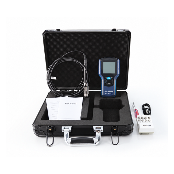
Keep the RS485 trunk as a controlled bus rather than an improvised star. Follow the delivered manual and controls design for polarity, topology, shielding, grounding and termination. Assign addresses on the bench, label both cable ends and retain an address schedule inside the panel documentation. Verify voltage at the farthest device while all loads are operating.
Polling should reflect process speed and bus loading. Faster is not automatically safer: excessive queries, retries or write commands can reduce network stability. The PLC should read only the required registers at a justified interval. Configuration and calibration writes should be restricted to authorized maintenance procedures and captured in a change record.
Maintenance access is part of data reliability. The bracket or flow cell should permit safe removal, cleaning and reference sampling without changing the represented process point. After service, require a stabilization and release rule before the measurement can control equipment again.
Prepare a Project-Ready Inquiry
For configuration review, provide:
- application, process point and the decision supported by each measurement;
- water matrix plus minimum, normal, alarm and maximum values;
- temperature, pressure, flow or level and expected fouling conditions;
- mounting drawing, cable route and length, available DC power and surge environment;
- PLC, RTU, data logger or gateway model and required protocol settings;
- parameters, quantity, polling, alarm behavior and data-retention requirements;
- destination, documentation language, delivery schedule and FAT/SAT scope.
Review the YEX-S2-MPS-A online multi-parameter water quality sensor, then Send Your Project Requirements with the tag list and host-system details. YexSensor can then confirm the applicable model, module combination, interface documents and accessories without transferring assumptions between products.
Frequently Asked Questions About Water Quality Sensor Data Contracts
Technical Questions
1. Is RS485 the same as Modbus RTU?
No. RS485 is the differential serial electrical layer, while Modbus RTU is a message protocol that can run on it. A purchase specification should state both and include baud rate, parity, data bits, stop bits, slave address and the model-specific register map. “RS485 output” alone does not confirm that the host knows the register, data type, scale, word order or unit.
2. Why must byte order and scaling be tested if communication is successful?
A valid Modbus response proves that the device answered; it does not prove that the PLC interpreted the bytes correctly. A two-register floating-point value can be assembled in the wrong word order, and an integer may require a scale factor. Test known or stable values at several points and compare the raw registers, converted tag and reference value before enabling alarms or control.
3. How should the PLC handle a sensor communication failure?
Mark the value bad or stale after the approved timeout and retry sequence, retain the last valid timestamp, and move automated equipment to the state defined by the control narrative. Do not convert a timeout into zero or continue control indefinitely from a retained value. The safe response depends on whether the measurement controls dosing, aeration, diversion, reporting or advisory display.
Selection Questions
4. When is a multi-parameter sensor preferable to separate probes?
Use a multi-parameter sensor when the selected parameters belong at the same representative point and can share mounting, service access and cleaning. Use separate probes when parameters belong at different hydraulic locations, need different materials or service intervals, or require independent redundancy. The ordered channel list and range for each module should be confirmed before the SCADA tag database is built.
5. Should every water quality value use the same polling interval?
No. Polling should reflect process response, alarm urgency, device behavior and total bus load. A fast neutralization process may justify a shorter interval than a slowly changing reservoir trend. Calculate the full multidrop cycle, include retries and allow margin. Record the chosen interval and stale-data limit per tag so the historian and alarm system interpret each measurement consistently.
6. Is Modbus always preferable to 4–20 mA for a retrofit?
Not always. Modbus can provide multiple values and status information over one bus, while 4–20 mA may fit an existing analog input and simpler control philosophy. Confirm the exact model’s available output rather than assuming both are simultaneous. Compare cable infrastructure, isolation, diagnostics, programming, spare inputs, maintenance capability and the consequence of a shared-bus failure.
Procurement and Project Questions
7. What interface documents should be delivered with the sensors?
Require the model-specific manual, approved datasheet, register map and revision, wiring diagram, ordered configuration, address schedule, calibration or inspection records, and FAT result where included. The register document should define function codes, addresses, data types, word order, scaling, units and writable commands. Document language and electronic file format should be listed in the quotation to avoid a handover gap.
8. What information should be included in the RFQ?
Provide the measurement purpose, water matrix, operating and upset ranges, temperature, pressure, flow or level, installation method, cable distance, power, host equipment, protocol settings, tag quantity, destination and schedule. Add alarm philosophy, reference method, testing scope and responsibility split. These inputs allow the quotation to cover a usable measurement point rather than an unspecified probe and generic communication claim.
9. How should distributor or EPC quotations be compared?
Normalize each offer to the same model, range, output, cable, mounting, cleaning, controller, protocol documents, calibration materials, spares, testing, warranty and delivery scope. Record exclusions and deviations separately. A lower sensor price is not directly comparable if another offer includes the flow cell, surge protection, register support, commissioning evidence or spare components needed for a maintainable installation.
10. Can one approved data contract be reused at multiple sites?
Yes, but only when the exact sensor model, firmware or register revision, ordered range, host conversion and process unit remain controlled. Site addresses, cable conditions, mounting, alarms and acceptance results still require local confirmation. Treat the approved contract as a versioned engineering template; do not silently reuse it after a model substitution or product-document revision.
Summary
A water quality sensor data contract turns protocol compatibility into an auditable engineering interface. It defines the exact device, serial settings, register interpretation, unit, timing, quality state, write authority and acceptance evidence before the value reaches PLC logic or a SCADA historian.
YexSensor products fit projects in which the selected model, water matrix and installation conditions are verified individually. Complete the design with representative mounting, stable DC power, controlled RS485 wiring, model-specific Modbus documentation, stale-data logic, maintenance access and end-to-end testing. For an accurate quotation, submit the parameter list, operating ranges, host details, cable distance, quantity, mounting plan and FAT/SAT expectations.



