


 Chinese
 Spanish
 French
 Russian
 German
 Portuguese
 Indonesian
 Thai
Thai Vietnamese
 Arabic

The radar flow meter working principle combines non-contact surface-velocity measurement, radar water-level measurement, a defined channel cross-section, and a correction factor to calculate open-channel discharge. For an integrator, the buying decision is therefore not just “which range is wider?” It is whether the site geometry, flow pattern, mounting position, communication architecture, and acceptance method can support a defensible flow result.

What Problem Does a Non-Contact Radar Flow Meter Solve?
Open channels differ from closed, full pipes. Water level and wetted area change, and surface velocity is not automatically the average velocity of the section. A workable system must measure the hydraulic variables and apply the correct channel model.
The YEX-HY-RFMS-01 radar flow meter sensor measures surface velocity and level above channels and rivers, then uses the configured cross-section and correction factor to calculate flow. RS485 Modbus RTU connects it to a PLC, RTU, SCADA system, or IoT gateway when power, address, baud, wiring, and register interpretation are correct.
This architecture addresses four buyer risks:
A submerged probe may be difficult to access or exposed to debris, sediment, and aggressive water.
A level-only instrument cannot calculate discharge without a separate hydraulic relationship or velocity input.
A velocity number is not yet a flow result until section geometry and the surface-to-average velocity relationship are defined.
A sensor that communicates in the workshop can still fail on site if addresses conflict, cable routing is poor, or the host polls faster than the instrument can respond.
Non-contact measurement reduces wet-end maintenance but does not remove hydraulic verification. Geometry, mounting angle, obstructions, eddies, and section changes remain uncertainty sources.
Radar Flow Meter Working Principle: From Surface Return to Discharge
1. Surface Velocity from Doppler Shift
The velocity radar operates at 24.00 GHz. It transmits a microwave signal toward the moving water surface. Surface features return the signal with a frequency shift related to their motion. The instrument converts that Doppler shift into surface velocity.
The benefit is physical separation from the water. The limitation is that radar observes a surface zone, not every velocity point. It must face the incoming flow, and the correction factor must represent the relationship between surface and average section velocity.
2. Water Level from Radar Distance
The 76–81 GHz level radar measures distance to the water surface. Reference height and section geometry then determine water depth and wetted area. Its verified distance range is 0.1–65 m, while operating installation height is 0–20 m; the wider distance range does not override the installation boundary.
3. Cross-Section and Correction Factor
Flow is calculated from average velocity multiplied by wetted cross-sectional area. Because the radar measures surface velocity, a correction factor is applied to estimate average velocity. The YEX-HY-RFMS-01 configuration supports rectangular and trapezoidal section inputs.
An incorrect width, side slope, zero-level reference, sediment condition, or borrowed coefficient can invalidate flow. Survey the section, document reference points, configure geometry, and compare discharge with an agreed field method.
4. Digital Output to the Monitoring System
The instrument outputs data through RS485 Modbus RTU. The manual specifies 8 data bits, no parity, one stop bit, and CRC checking. The default address is 0x01 and the default baud rate is 4800 bps; configurable baud rates include 1200, 2400, 4800, 9600, 19200, 38400, 57600, and 115200 bps.
Assign unique addresses on a multidrop network and map level, velocity, and flow into the host. The purchase order should identify the approved register map and units; scaling from another model must not be reused.

Verified YEX-HY-RFMS-01 Parameters and Their Project Meaning
These values come from the current YEX-HY-RFMS-01 manual and product page and apply only to this model. Confirm the ordered revision, nameplate, cable, accessories, and protocol document.
| Selection item | Verified specification | What it means for the buyer |
|---|---|---|
| Power supply | DC 10–30 V | Compatible with common DC field supplies; size the supply and voltage drop for the full cable run, surge protection, controller, and communications equipment |
| Maximum power | 1.3 W | Supports low-power remote station design, but the complete solar/battery budget must also include the RTU, modem, heater or enclosure loads if used |
| Operating environment | −40 to +80 °C; 0–95% RH, non-condensing | Check solar heating, condensation, icing, enclosure ventilation, connectors, and cable entry rather than using ambient temperature alone |
| Velocity radar frequency | 24.00 GHz | Identifies the non-contact Doppler velocity channel; it should not be confused with the separate level radar frequency |
| Velocity range | 0.1–20 m/s | Suitable only when credible minimum and maximum surface velocity remain within the stated range; near-stagnant sites require another approach or field validation |
| Velocity accuracy | ±2% | Use this as one component of system uncertainty; section survey, flow profile, coefficient, mounting, and hydraulic conditions also affect discharge accuracy |
| Velocity resolution | 0.01 m/s | Supports trend resolution at the sensor output, but resolution is not the same as total flow accuracy |
| Level radar frequency | 76–81 GHz | Provides the non-contact distance measurement used to determine water level and wetted area |
| Water-level distance range | 0.1–65 m | Confirm the closest and farthest water-surface distances through dry, normal, and flood conditions |
| Distance accuracy | ±1 mm | Useful for level determination in a stable reference installation; structural movement and an incorrect zero reference can still dominate the field result |
| Distance resolution | 1 mm | Defines reported distance increments, not the accuracy of calculated discharge |
| Operating installation height | 0–20 m | Use this installation boundary when selecting bridge, pole, or gantry location; do not select from the 65 m distance range alone |
| Output | RS485 Modbus RTU | Enables PLC, RTU, SCADA, and IoT integration after address, baud, framing, register map, units, and polling interval are approved |
| Standard supplied cable | 5 m waterproof plug-in cable | Check actual route, junction location, UV exposure, mechanical protection, and required extension before ordering |
| Supplied mechanical items | Mounting bracket and mounting screws | Confirm that the supplied bracket suits the project structure; poles, bridge fixtures, custom steelwork, and civil works may remain in the contractor scope |
Who Should Select YEX-HY-RFMS-01—and Who Should Not?
Suitable project profiles
YEX-HY-RFMS-01 suits open channels, drains, canals, and rivers where keeping the velocity sensor out of the water reduces cleaning and access risk. It also fits remote RS485 Modbus RTU stations needing level, surface velocity, and calculated flow from one device.
It is a stronger fit when the site offers a stable, regular section; straight and concentrated flow; a clear radar view; a rigid mounting structure; and access for section survey and commissioning checks. The manual recommends placing the instrument near the channel or river center and selecting a section without large rocks, vortices, turbulence, or accumulated floating debris.
Projects that need a different solution
It is not the first choice for a full, pressurized pipe. Use caution where geometry changes continuously, the beam is obstructed, velocity is normally below 0.1 m/s, or overhead mounting is impractical.
For water level only, select YEX-HY-RWLS-01. For direct in-water velocity, compare a Doppler meter. A continuously full pipe requires a pipe-flow technology, not a forced open-channel method.
Radar Flow Meter vs Submerged Doppler and Level-Only Radar
Compare hydraulic conditions and maintenance exposure, not one headline range.
| Decision point | YEX-HY-RFMS-01 radar flow meter | YEX-HY-DFM-01 Doppler flow meter | YEX-HY-RWLS-01 radar level sensor |
|---|---|---|---|
| Primary function | Non-contact surface velocity, level, and calculated flow | Submerged ultrasonic Doppler velocity, level, and calculated flow | Non-contact water level only |
| Verified velocity range | 0.1–20 m/s | 0.03–10 m/s | Not applicable |
| Verified level/distance range | 0.1–65 m distance; 0–20 m operating height | 0.03–5 m level | 0.1–65 m distance |
| Water contact | No | Yes; sensor installs at least 20 cm below the minimum water level | No |
| Protection information | Outdoor waterproof design stated in the RFMS manual | IP68 | Confirm ordered product documentation |
| Communication | RS485 Modbus RTU | RS485 Modbus RTU | RS485 Modbus RTU |
| Better project fit | Overhead access, debris or sediment concerns, regular open section | Stable submerged mounting and suitable water depth, including lower velocity duty | Level monitoring or a project with a separate rating curve/flow method |
| Key procurement risk | Incorrect cross-section, correction factor, beam alignment, or unstable hydraulics | Burial, fouling, debris impact, cable protection, or insufficient submergence | A level value may be wrongly presented as measured flow without an approved conversion method |

Application Scenarios for Integrators and Project Contractors
River and Flood Monitoring
Field challenge: Rapid level and velocity changes make high-flow access unsafe and expose submerged equipment to debris.
Integration approach: Use a rigid bridge, pole, or gantry above a surveyed section. Send level, velocity, and flow by RS485 to the RTU and flag values outside the validated hydraulic envelope.
User value: Operators gain remote trends without routine water entry, provided the section reference and flood behavior remain validated.
Irrigation Canal Flow Measurement
Field challenge: Sediment, weeds, gates, and changing levels affect canal allocation data.
Integration approach: Select a straight section away from gates, drops, pumps, and bends. Configure surveyed geometry and compare low, normal, and high-flow results.
User value: The station provides continuous trends with less wet-end cleaning; re-survey follows sediment or construction changes.
Urban Drainage and Stormwater Monitoring
Field challenge: A low-flow drain may become a fast, debris-laden channel during inaccessible storm events.
Integration approach: Verify dry-weather velocity, protect power and communications against surge, and configure realistic jump thresholds and alarms.
User value: The contractor gains remote event records and safer access. Near-stagnant or surcharged conditions may require another method or location.
Industrial and Environmental Discharge Channels
Field challenge: Corrosive water increases wet-end maintenance while discharge reporting requires traceable configuration.
Integration approach: Survey the channel, record the correction factor, lock approved Modbus scaling and units, and define independent checks.
User value: The plant reduces direct contact with wastewater; the owner must still approve the reporting method and acceptance procedure.
Installation and RS485 Modbus Integration Checklist
The manual recommends approximately 3–4 m for many installations. Excessive height weakens return and enlarges the footprint; low mounting increases tampering risk. Final height must respect the 0–20 m operating boundary and water levels.
Keep the casing level and aim the velocity beam upstream at 0° horizontally to the flow. The level beam is about 6° × 6° and the velocity beam about 30° × 80°; check structures and vegetation against both footprints over the full level range.
Use DC 10–30 V, correct RS485 A/B polarity, unique addresses, an approved topology, and suitable shielded cable. Separate signal wiring from interference. For long networks, assess local power, a repeater, and 120-ohm termination. Allow more than 200 ms for polling and response during troubleshooting.
Commissioning should verify:
Model, serial number, cable, bracket, manual, warranty card, and certificate of conformity.
Mounting position, structural rigidity, beam clearance, alignment, water-level reference, and surveyed section dimensions.
Power voltage at the device under load, polarity, grounding, surge protection, and cable protection.
Modbus address, baud, register map, units, byte order, polling, timeout, and exception handling.
Level, velocity, calculated flow, correction factor, thresholds, alarms, and historian tags.
An agreed comparison with an independent field method, plus ownership of future section surveys and configuration changes.
Price, Customization, Delivery, Packaging, and After-Sales Checks
Radar flow meter price includes more than the sensor. Model, cable, steelwork, DC supply, surge protection, RTU or gateway, telemetry, cabinet, survey, commissioning, quantity, destination, and trade terms all matter. Separate included items, options, and contractor scope.
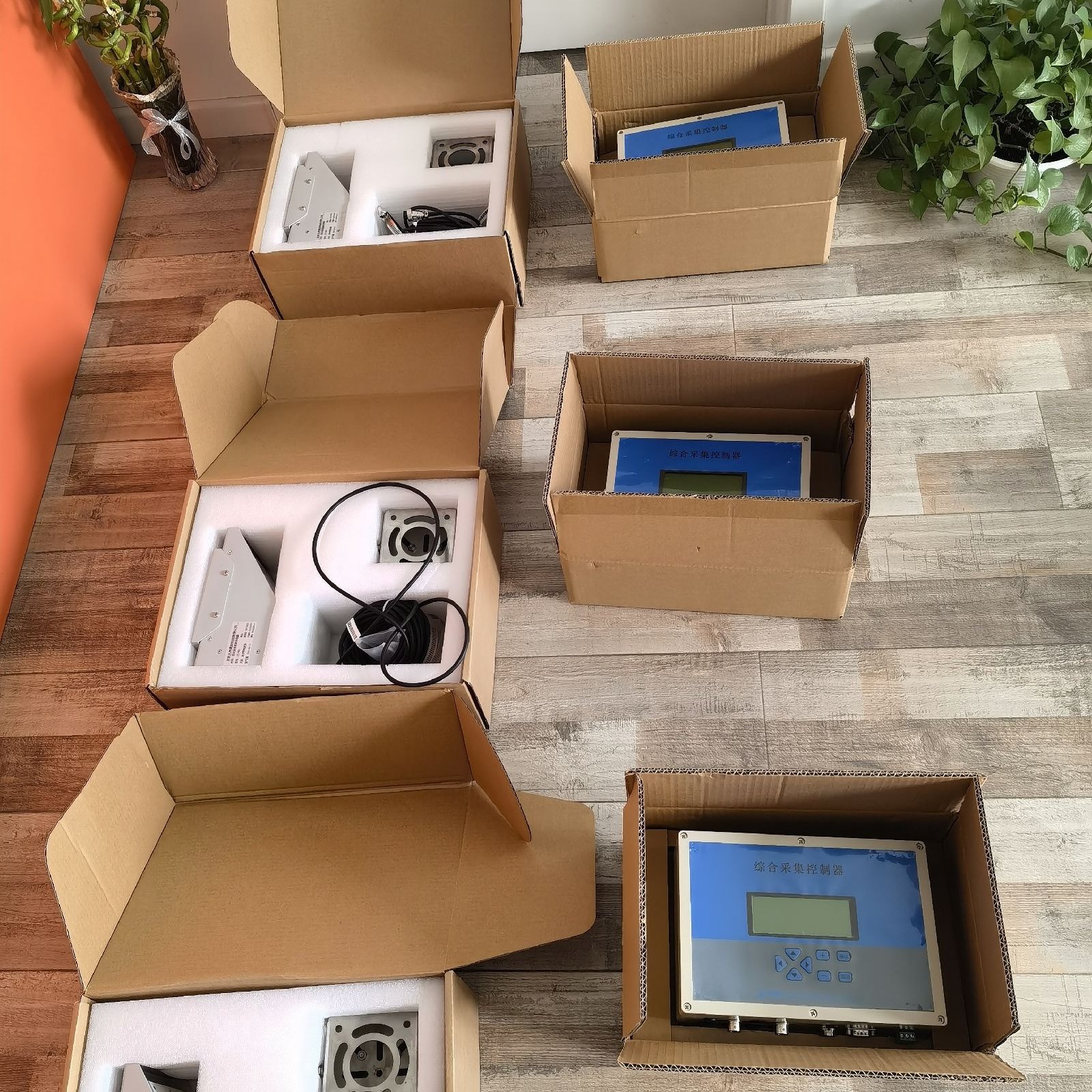
The manual lists the meter, 5 m waterproof plug-in cable, bracket, screws, warranty card, and certificate of conformity. The reference image shows foam-lined cartons and separately boxed controllers; it does not prove that every order includes a controller or identical carton. Confirm export packing, dimensions, weight, moisture protection, palletization, and labels.
MOQ, production lead time, shipping schedule, warranty duration, certification documents, inspection reports, and return procedure are not fixed in the public product specification. Put them in the quotation and purchase order. If the project needs a longer cable, custom bracket, preset address, private label, specific documentation language, FAT records, or gateway configuration, describe the requirement and request written feasibility confirmation. “Customization available” is not sufficient without a drawing, revision, acceptance test, price, and lead-time impact.
Name responsibility for hydraulic verification, Modbus support, replacement assessment, returns, remote troubleshooting, and site labor. Keep an approved parameter sheet and configuration record with the asset.
Illustrative Project Design Example: Municipal Drainage Outfall
For a trapezoidal drainage outfall with an RTU and cellular modem, the team first surveys the section, verifies velocity above 0.1 m/s, checks maximum level and clearance, and avoids gates, drops, and eddies. The radar mounts on rigid steelwork; the RTU polls its unique Modbus address and stores level, velocity, flow, status, and quality flags. Commissioning compares several flows with an independent method and records the correction factor. This is a design example, not a named customer claim.
Frequently Asked Questions About the Radar Flow Meter Working Principle
1. Does a radar flow meter measure flow directly?
Not directly. YEX-HY-RFMS-01 measures surface velocity and water-surface distance, then uses a configured rectangular or trapezoidal section and correction factor to calculate flow. Commissioning therefore needs a section survey, level reference, coefficient review, and field comparison. A factory value without site geometry is not a defensible discharge result.
2. Why does surface velocity need a correction factor?
Velocity varies across an open channel, while radar observes a surface zone. The correction factor relates surface velocity to the average velocity used for discharge. Roughness, depth, bends, structures, vegetation, and sediment alter that relationship. Validate and document the factor under representative conditions instead of copying one from another site.
3. How does RS485 Modbus RTU integration work for YEX-HY-RFMS-01?
It uses RS485 Modbus RTU with 8 data bits, no parity, one stop bit, and CRC. Default address is 0x01 and default baud is 4800 bps. Each device needs a unique address. Approve polarity, topology, register map, units, byte order, timeout, and more than 200 ms for polling and response during troubleshooting.
4. When should I choose radar instead of a submerged Doppler flow meter?
Choose radar for a clear overhead view, stable section, suitable velocity, and rigid mounting, especially where debris or contamination makes submergence undesirable. Choose YEX-HY-DFM-01 when an in-water point is acceptable and its 0.03–10 m/s velocity and 0.03–5 m level ranges fit. Compare hydraulics and maintenance before price.
5. Is YEX-HY-RFMS-01 suitable for very slow or stagnant water?
The verified range begins at 0.1 m/s. If normal or decision-critical velocity is lower, the wide maximum range does not solve the application. Provide minimum velocity, dry-weather conditions, and reporting threshold, then assess another location, a submerged Doppler model, a level-based method, or a validation trial.
6. Can the radar flow meter be installed over any channel shape?
No. It supports rectangular and trapezoidal section inputs and favors a stable, regular section with straight flow. Irregular beds, sediment changes, rocks, vortices, turbulence, and debris increase uncertainty. Submit surveyed geometry and photographs. If the section changes, schedule re-survey and configuration control.
7. What determines the quoted radar flow meter price?
Price depends on cable, bracket or steelwork, power and surge protection, controller or gateway, telemetry, cabinet, survey, commissioning, documents, spares, quantity, packing, destination, and trade terms. Request a line-item scope so a sensor-only offer is not compared with a complete station.
8. What are the MOQ, lead time, warranty, and certification options?
These terms are not fixed in the public specification. Confirm them for the quantity, destination, and document requirement. The manual lists a warranty card and certificate of conformity but does not support claims for every third-party certification. Put certificates, reports, warranty duration, response process, shipment date, and acceptance documents in the order.
9. What information should a distributor or integrator send before requesting a quotation?
Send the application, channel drawing, photographs, level and velocity ranges, flow range, mounting height, obstructions, environment, power, cable, host, Modbus settings, quantity, documents, acceptance method, destination, and schedule. Mark unknown values as survey tasks. A complete RFQ lets YexSensor identify fit and exclusions without unverified assumptions.

Summary
The radar flow meter working principle is useful only when surface velocity, water level, cross-section geometry, correction factor, mounting, and data integration are treated as one measurement system. YEX-HY-RFMS-01 fits non-contact open-channel projects that have a clear overhead view, a stable rectangular or trapezoidal section, credible velocity from 0.1 to 20 m/s, suitable mounting within the 0–20 m operating-height boundary, and an RS485 Modbus RTU host.
It is not the automatic choice for full pipes, near-stagnant water, unstable sections, obstructed beams, or projects that only need level. Those conditions may favor a submerged YEX-HY-DFM-01 or YEX-HY-DFM-02, a YEX-HY-RWLS-01 level sensor, another measurement point, or a different flow technology.
Before purchase, verify section drawings, hydraulic ranges, beam clearance, mounting steelwork, DC power, cable length, Modbus settings, register units, validation method, controller and telemetry scope, packaging, documentation, warranty, delivery, and after-sales responsibility. If the model choice is uncertain, send the site conditions, required output, quantity, destination, and project schedule to YexSensor so the quotation can match the actual measurement boundary rather than a generic product list.



