


 Chinese
 Spanish
 French
 Russian
 German
 Portuguese
 Indonesian
 Thai
Thai Vietnamese
 Arabic

A dependable water quality monitoring system is not a sensor connected to a dashboard. You need a representative measurement point, verified parameter modules, stable power, documented Modbus data, maintainable installation, quality flags and a defined response to alarms before an IoT or SCADA platform adds value.
Why Monitoring-System Projects Fail After the Sensor Works
Integrators usually prove that a sensor returns a number during a bench test. The harder question is whether the number remains representative after months in a channel, tank, reservoir or treatment process. Fouling, sediment, bubbles, flow changes, lightning, voltage drop, damaged connectors, address conflicts and undocumented scaling can all create data that looks credible but is wrong.
A system should separate measurement status from the measured value. A timeout, maintenance period, calibration command or cleaning cycle must not appear as a real zero. The platform should retain raw value, engineering value, quality flag, device status, timestamp and maintenance state. This allows operators and future analytics to distinguish process change from instrument condition.
Water Quality Monitoring System Architecture
| Layer | Engineering responsibility | Procurement evidence |
|---|---|---|
| Measurement | Correct parameter, range, principle and material for the water matrix | Model-specific datasheet, manual and ordered module list |
| Mechanical | Representative flow, depth, protection, retrieval and cleaning access | Drawing, bracket or flow-cell details, cable route and service method |
| Electrical | Power at load, polarity, shielding, grounding and surge protection | Power budget, wiring diagram and cabinet protection schedule |
| Field data | Addresses, registers, units, scaling, byte order, polling and faults | Delivered Modbus map and bench-test record |
| Backhaul | Ethernet, cellular or other network between gateway and platform | Gateway configuration, SIM/service scope and cybersecurity ownership |
| Operations | Alarms, validation, maintenance, retention and response | Commissioning plan, SOP, alarm matrix and acceptance report |
RS485 is the differential serial electrical layer; Modbus RTU is the application protocol. A project specification should state both. The host also needs the actual registers, data type, word order, scale and unit. “RS485 compatible” does not prove that a PLC program can interpret the delivered device.
Verified YEX-S2-MPS-A Integration Boundaries
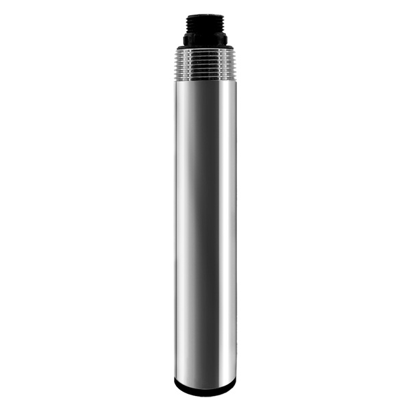
The YEX-S2-MPS-A is a configurable online multi-parameter self-cleaning platform. It can carry up to eight parameters including temperature, with optional dissolved oxygen, optical COD, pH, ORP, conductivity or salinity, ammonium nitrogen and turbidity modules. The exact combination is an ordered configuration, not a standard set of eight sensors.
| Selection item | Verified specification | Project meaning |
|---|---|---|
| Channels | Up to eight parameters including temperature | List every module, range, unit and calibration method in the purchase order |
| Field protocol | RS485 Modbus RTU | Obtain the delivered register map and restrict write functions |
| Default serial format | 9600 bps, no parity, 8 data bits, 1 stop bit | Match the host and document any project-specific change |
| Address | Default 6; configurable 1–255 | Assign unique addresses before a multidrop network is assembled |
| Power | 12 VDC ±5% | Check voltage at the probe under load and include cable drop and surge conditions |
| Automatic cleaning | 6–6000 minute interval; 0–10 rotations; default 30 minutes and 3 rotations | Use site evidence to set the cycle and continue physical inspection |
Specification basis: the integration values above were checked against the current YexSensor information for the YEX-S2-MPS-A configuration on October 6, 2026. Parameter modules and their measurement specifications remain model-specific. Confirm the ordered module list, protocol map, accessories and acceptance criteria in the approved quotation.
Optical COD is a continuous trend technology and is not the same as reagent digestion followed by photometry. If a contract requires a reference COD procedure, retain the prescribed sample, digestion, quality control and laboratory reporting. This boundary should appear in the data dictionary so users do not treat values from different methods as interchangeable.
Multi-Parameter Sonde or Separate Sensors?
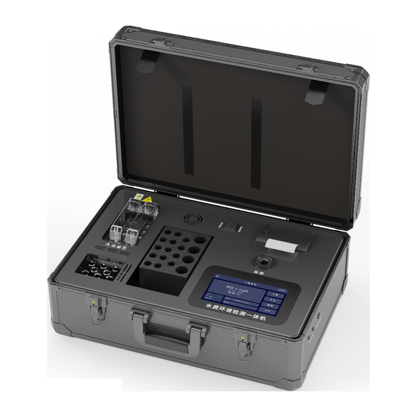
Choose an integrated sonde when several parameters share one representative point and one service team. One mount, cable, cleaning mechanism and Modbus address reduce installation work. This is useful for river stations, reservoirs, landscape water, aquaculture, wastewater channels and OEM cabinets with limited maintenance access.
Choose separate sensors when DO belongs in an aeration basin but conductivity belongs at a reuse outlet, or when one critical parameter requires redundant measurement. Separate probes also make sense when materials, ranges, replacement intervals or cleaning methods differ. A larger integrated probe can be difficult to place in a narrow bypass, and one common location may be technically convenient but not process-representative.
Application Scenarios with System Decisions
Municipal wastewater treatment
Challenge: aeration, solids and nutrient conditions change across stages. System: position DO where flow represents biological demand, pH near dosing decisions and turbidity or solids at clarification. Connect each node to the PLC with explicit invalid-data logic. Value: control uses the right point instead of a convenient common location.
River and reservoir stations
Challenge: biofilm, debris, changing water level and remote power create data gaps. System: use a serviceable protective mount, automatic cleaning, solar power budget, local buffering and cellular gateway. Value: the station retains evidence through network outages and can be retrieved without entering unsafe water.
Aquaculture and recirculating systems
Challenge: oxygen can fall quickly and salinity affects interpretation. System: combine continuous DO, temperature, pH and conductivity with alarms, aeration interlocks and portable verification. Value: operations can respond to risk while confirming whether a fixed probe is fouled or poorly placed.
Industrial discharge and reuse
Challenge: short batch events can be missed by manual sampling. System: use continuous trend sensors before the decision point and route alarms to responsible operators; retain laboratory confirmation where required. Value: the plant gains earlier warning without confusing screening data with contractual compliance.
Modbus, Gateway and SCADA Commissioning
Create a register schedule before software development. Record device model, firmware, address, function code, register, data type, word order, decimal scale, unit, valid range, status code and write permissions. Bench-test the delivered probe, cable, power supply and host—not a simulated device—before the cabinet ships.
Use conservative polling and retry logic. A multidrop bus needs unique addresses, appropriate topology, twisted shielded cable, controlled grounding and termination only where required. Long stubs and star wiring increase reflections. Route communication away from variable-frequency drives and high-current conductors. Verify voltage at the farthest probe during cleaning and transmission. Use the RS485 Modbus water quality sensor integration guide to structure wiring, polling and fault-state checks.
The gateway should publish a timestamp and quality state with each value. Define local storage during backhaul failure, retry behavior, clock synchronization, certificate or credential ownership, and what happens when cloud service expires. These are system-scope questions; they are not solved by the sensor register map.
Cleaning, Validation and Acceptance
Automatic brush cleaning reduces soft deposits but does not remove scale, oil, damaged optics or exhausted electrodes. Begin with frequent inspection and record the condition before and after cleaning. Extend the interval only after field evidence shows that values remain stable. Include safe retrieval, rinse water, standards, spare seals and waste handling in the maintenance plan.
Commission each channel against an appropriate reference under representative conditions. Record as-found value, reference result, temperature, flow, sample time, adjustment, as-left value and operator. Test alarms, timeouts, cable disconnection, restart, gateway failure, data buffering and cleaning status. Acceptance must demonstrate the whole path from water to dashboard, not only a local sensor display.
Data rule: never map communication failure to zero. Use an invalid flag, hold-last-value marker or explicit fault state according to the control philosophy. A plausible false value is more dangerous than a visible data gap.
Life-Cycle Cost and Expansion Planning
The purchase price is only one part of a monitoring station. Budget site visits, standards, replacement electrodes or optical components, cleaning parts, seals, desiccants where applicable, calibration labor, gateway service, SIM or platform fees, surge damage and safe access. A remote station with lower-cost probes can become expensive if fouling forces weekly travel or if proprietary data prevents integration.
Plan expansion before assigning addresses and tags. Reserve sensible address ranges, cabinet power, terminals, serial-bus capacity and platform names without creating unsupported stubs. Record the maximum devices and polling load accepted by the controller. If a future parameter needs a different location, provide a new field node rather than extending a convenient sonde beyond its representative sampling point.
Define spare strategy by consequence and lead time. A critical aeration or discharge channel may justify a ready spare probe, while a noncritical trend parameter may use a shared service spare. Keep configuration backups, firmware identity, protocol documents, calibration history and part numbers with the asset record. These details shorten recovery and prevent a replacement device from silently using a different address, scale or unit.
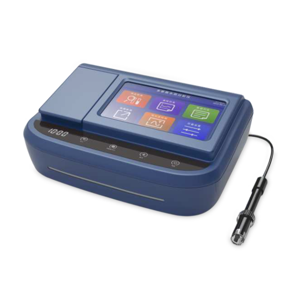
Provide parameter modules and ranges; water matrix and fouling; every measurement point; mounting, depth and cable length; power and surge environment; PLC, RTU or gateway model; Modbus settings; platform protocol; storage and alarm logic; cleaning and calibration plan; quantity, destination and schedule. Review the multi-parameter water quality monitoring guide; for an independently mounted turbidity channel, review the YEX-S1PRO-TUR Modbus sensor. Then Send Your Project Requirements.
FAQ About Water Quality Monitoring Systems
Technical questions
1. What are the main layers of a water quality monitoring system?
A complete system includes sensing, mechanical installation and cleaning, field power and electrical protection, PLC/RTU/gateway, backhaul communications, data platform and operating response. The quotation should assign responsibility for every layer. Buying only sensors leaves unresolved work around mounting, registers, alarms, storage, maintenance and acceptance. Name the party responsible for each interface.
2. Can RS485 connect directly to an IoT cloud?
No. RS485 is a field electrical interface and Modbus RTU provides device messaging. A compatible PLC, RTU or gateway must poll the registers, validate the response and publish data through MQTT, HTTP, TCP or the platform’s required protocol. Confirm the gateway and service scope separately from the probe. Include network credentials and renewal ownership.
3. How should a communication failure be represented?
Use an explicit invalid state or quality flag, not a real zero. The platform should retain the last valid timestamp and distinguish timeout, sensor fault, cleaning, calibration and maintenance. Control logic must define its safe response. Test these states during FAT and site acceptance, including cable removal and gateway outage.
Selection questions
4. When is a multi-parameter sonde appropriate?
Choose it when several parameters share one representative location and the project benefits from one mounting assembly, cable, cleaning mechanism and Modbus node. It fits remote stations and compact OEM systems. Confirm that every module fits the matrix, range and maintenance interval rather than ordering the maximum channel count automatically.
5. When are separate sensors preferable?
Use separate sensors when parameters require different process locations, materials, ranges, redundancy, cleaning or replacement intervals. They can also simplify narrow flow-cell installation and critical-channel replacement. Compare total mounts, cabling and service visits against the risk of forcing all measurements into one technically convenient but unrepresentative location. Critical channels may also require independent redundancy.
6. Does automatic cleaning eliminate maintenance?
No. A brush reduces soft biofilm and sediment on accessible surfaces. It cannot correct scale, oily coating, damaged optics, exhausted electrodes, blocked guards or poor placement. Start with frequent inspection, record as-found condition and adjust the cycle from site evidence. Budget standards, cleaning materials, seals and replacement modules. Verify readings after every maintenance intervention.
Procurement and project questions
7. What determines monitoring-system price?
Cost depends on channels, ranges, probe materials, cable, bracket or flow cell, cleaning, controller, gateway, power, solar equipment, enclosure, platform service, documentation, spares, training and commissioning. Compare the complete installed and maintained system. A low probe price does not cover cabinet, network or field-service responsibilities. Include recurring data-service charges over the contract life.
8. What should the system RFQ include?
List parameters, ranges, water conditions, measurement locations, installation, depth, cable, power, PLC or gateway, Modbus settings, cloud protocol, storage, alarms, maintenance access, validation method, quantity, destination and schedule. Attach drawings and controller details so YexSensor can verify the delivered protocol and hardware scope before purchase. State FAT and site-acceptance responsibilities explicitly.
Summary
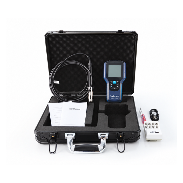
A water quality monitoring system succeeds when sensing, mechanical installation, power protection, RS485 Modbus, gateway conversion, platform logic and operating response are designed as one architecture. YEX-S2-MPS-A fits a representative multi-parameter point requiring an ordered module set and automatic cleaning. Separate YexSensor probes are preferable when parameters require different locations, materials, ranges, redundancy or maintenance intervals. Portable and laboratory instruments should remain independent verification layers rather than substitutes for continuous control.
Before ordering, freeze every module and range, measurement point, mount, cable, power source, register map, address plan, quality flag, alarm, cleaning cycle, validation method and acceptance test. Include the PLC, RTU or gateway model, cloud protocol, data ownership, service responsibilities, quantity, destination and schedule in the RFQ. These decisions determine whether the delivered project creates defensible operational information or only displays unverified values.



