


 Chinese
 Spanish
 French
 Russian
 German
 Portuguese
 Indonesian
 Thai
 Vietnamese
 Arabic


An RS485 water quality sensor not communicating with a PLC should be investigated as a power, wiring, configuration or transaction problem before it is treated as a failed probe. Start with one device and a verified read request, then restore the complete network only after the basic connection works.

RS485 water quality sensor not communicating: identify the failure first
Record the actual symptom: no received bytes, corrupted frames, a Modbus exception, intermittent timeouts or a valid response containing an implausible value. These observations lead to different checks. Replacing hardware without distinguishing them can preserve the fault and add another configuration change to the investigation.
RS485 describes an electrical interface; Modbus RTU defines a communication method used by many industrial sensors. Matching the connector or bus wiring is not enough. The controller must implement the protocol and interpret the supplied device's register map. A compatible-looking serial port may still require a correctly configured master function or gateway.
Record changes; acceptance requires reproducible communication.
Follow a symptom-led diagnostic sequence
| Observed symptom | First check | Evidence required before replacement |
|---|---|---|
| No response at all | Loaded supply, wiring and serial settings | One known device tested with a valid request. |
| CRC or framing failures | Serial format, wiring condition and electrical disturbance | Error record correlated with settings or site events. |
| Modbus exception returned | Requested function, register and count | Decoded exception compared with the model's map. |
| Intermittent timeouts | Address conflicts, polling and supply behavior | Logs showing when communication is lost and recovered. |
| Valid frame, wrong value | Unit, scaling, signedness and word order | Raw register values compared with approved interpretation. |
Preserve transmitted and received frames, PLC settings and test conditions. Silence alone does not establish a failed probe.
Step 1: establish power and the physical connection
Check the delivered wiring diagram and measure the supply at the sensor connection under load. A nominal voltage at the cabinet supply does not exclude voltage drop, a loose terminal or an intermittent return path. Isolate power before rewiring and follow the project's electrical safety procedure.
Check polarity against both manuals; wire colors and A/B conventions may differ. Inspect terminals, insulation, moisture and cable joints. Repairs must restore environmental protection as well as continuity.
Then inspect bus topology and the installed termination and biasing arrangement. Do not add a resistor to every sensor as a universal remedy. Follow the host and device requirements and the applicable serial-line guidance. Record existing built-in components before adding external ones, because duplicated termination or biasing can create a different fault.
The Modbus Organization serial-line implementation guide provides the protocol reference. Use it alongside the delivered sensor and controller documents; it does not supply the register map for an individual YexSensor model.
Step 2: prove one device before diagnosing the full bus
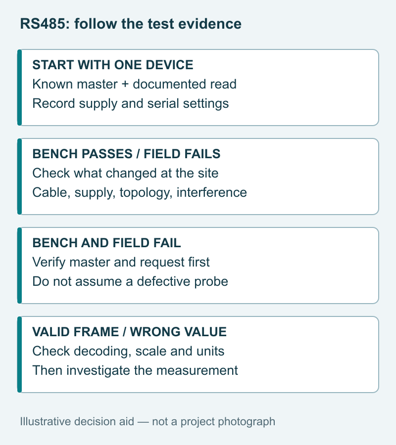
Under an approved test arrangement, disconnect the production bus and test one sensor on a short, suitable connection with a known master. Preserve any control safeguards while the sensor is unavailable. Match baud rate, parity, stop bits and address to the actual device configuration; there is no universal YexSensor default established for every model in this guide.
Request only a documented readable item using the specified function and register count. Avoid exploratory writes, reset commands or undocumented calibration registers. A diagnostic test should not change the measuring behavior merely to discover whether communication is possible.
If the bench test passes but the field connection fails, investigate the changed cable, supply and electrical environment. If both fail, verify the master and request against a known working setup before suspecting the probe. If valid frames contain wrong values, proceed to decoding rather than rewiring. Restore multiple devices individually with unique addresses.
Step 3: verify register interpretation and polling behavior
Confirm how the PLC represents register addresses. A manual's register label and a software driver's starting offset may differ. Also confirm data type, number of registers, units, multiplier, signed values and word order where multi-register data is used. Do not solve a mismatch by trying arbitrary combinations on a live control loop.
Separate communication speed from measurement update rate. Reading faster does not necessarily produce fresher measurements. An unnecessarily aggressive request cycle can create congestion or retries without improving the useful trend. Use documented response behavior and the project's update requirement to establish polling, timeout and retry settings.
If a valid conductivity value differs from a reference meter, move to measurement diagnosis rather than continuing to change serial settings. The conductivity temperature compensation checks explain one common source of disagreement after communication has already been established.

Product evidence: similar interfaces do not mean identical maps
The following examples use the corresponding model manuals. A shared interface does not establish interchangeable registers, outputs or installation requirements. Confirm the exact part number and document revision supplied with each order.
| Model | Manual specification | Integration decision |
|---|---|---|
| YEX-S1-EC | RS485 Modbus RTU; 12–24 V DC | Confirm conductivity units and temperature-compensation interpretation. |
| YEX-S1-RDO | RS485 Modbus RTU; 0–20 mg/L | Distinguish dissolved-oxygen concentration from any saturation output. |
| YEX-S2-CL-S | RS485 Modbus RTU; optional 4–20 mA; 12–24 V DC | Specify the ordered output and chlorine reporting basis. |
| S1-EC and S1-RDO cable | Standard 5 m; other lengths customizable | Confirm the approved extension and termination for the installed route. |
| Environmental and metrological limits | Model-specific, not determined by RS485 | Obtain pressure, temperature, accuracy, power and material specifications separately. |
Review the YEX-S1-EC, YEX-S1-RDO and YEX-S2-CL-S product information for those distinct duties. The presence of IP68 on a probe does not protect an exposed cabinet terminal or an unsealed field splice.
Three project situations and their practical response
OEM skid works in the workshop but fails after delivery
Compare the field cable route, host and electrical environment with the verified workshop arrangement. Test one device under controlled conditions. This identifies changed conditions before probe replacement or extensive PLC rewrites.
A remote station loses several channels together
Correlate simultaneous timeouts with voltage, pump operation and gateway status. Inspect shared wiring and address allocation before replacing several probes. Display a network outage as unavailable data, not water-quality improvement.
A mixed-sensor panel displays believable but wrong values
The challenge is using one copied register interpretation for different models. Verify each map, unit and data type against raw responses, then assign separate channel definitions. The value is a commissioning record that connects the device label to the PLC tag and final display. These situations are illustrative diagnostic patterns, not measured customer results.
Procurement and acceptance: buy the documentation with the device
Require a completed transaction record for each tag, not merely a screenshot. Assign driver ownership and include commissioning support in the supply scope.
| Record field | Capture during acceptance |
|---|---|
| Device identity | Tag, model, serial number, map revision. |
| Physical test | Bench or field, loaded voltage, cable route. |
| Serial setup | Address, baud rate, parity, stop bits. |
| Transaction | Function, start offset, count, raw request and response. |
| Interpretation | Data type, unit, multiplier, decoded value. |
| Reliability | Test duration, error count, timeout and recovery behavior. |
Test loss and recovery under the approved procedure, including timestamps and retained values. Modbus is not a certified safety function. Price adapters, protection, field support and spares separately; confirm lead time and warranty for the ordered model.
Project configuration review
Share the sensor model and label, manual revision, PLC or gateway model, topology, cable length, supply measurements, serial settings and captured request/response example. Include the symptoms, previous working configuration, quantity and commissioning schedule. Review the relevant RS485 conductivity sensor configuration if it matches your point, then Send Your Project Requirements for a model-specific review.

Frequently asked questions
Q1. RS485 water quality sensor not communicating: where should I start?
Start with the actual fault symptom, loaded supply and delivered wiring diagram, then confirm serial settings and a documented read request. Test one sensor before restoring a shared bus. Keep configuration and response records so the supplier can distinguish an installation issue from a device fault without guessing from a screenshot of a blank display.
Q2. Does a Modbus exception mean the probe is defective?
No. A valid exception indicates that a device received a request and returned an error response. Check the exception meaning, function, register address and requested count against the matching manual. Do not replace the probe solely because the PLC reports an exception. Include the raw transaction and document revision when requesting technical support.
Q3. Why can communication succeed while the reading is wrong?
The host may interpret a valid response using the wrong unit, scale, signedness or multi-register order. A separate measurement issue can also exist after communication is working. Compare raw values with the approved map and a suitable reference check. Resolve interpretation first; changing calibration to compensate for an incorrectly decoded value creates another error.
Q4. Should I replace RS485 with an analog output?
Only after defining what the project needs and identifying the fault. Analog inputs may suit an existing cabinet, but they introduce their own scaling and fault-detection requirements. An optional 4–20 mA output is model-specific. Compare the complete interface arrangement, required variables and diagnostics before buying different hardware to solve an unproven communication problem.
Q5. Can different sensor models share the same bus?
Potentially, if their electrical arrangements, protocol settings and host capabilities are compatible. Each device needs a unique address and its own correct register interpretation. Confirm topology, loading and timing with the actual equipment documents. Procurement should require a channel schedule and compatibility test rather than assuming that identical connector shapes or supply voltages establish interoperability.
Q6. When is an isolated interface worth specifying?
Consider isolation when the electrical design identifies common-mode or grounding risks across the installation. It is not a substitute for correct wiring or a universal cure for every timeout. Have the responsible engineer review the host, supply, cable route and protection arrangement, then include the required isolation and surge components explicitly in the quoted scope.
Q7. What records should accompany a replacement sensor?
Keep the exact model, hardware or firmware identifier where available, configuration, register-map revision and original acceptance record. Verify the replacement's address and settings before connecting it to a shared bus. Ask the supplier to identify any relevant revision differences so a maintenance purchase does not silently introduce a different data interpretation or commissioning requirement.
Q8. Which support information reduces commissioning delays?
Provide a topology sketch, terminal photographs, measured supply, controller model, serial settings and a short raw communication log. State whether the failure occurs on the bench, at startup or during specific equipment operation. Include the delivery and commissioning schedule. This evidence helps the responsible supplier or integrator narrow the fault without requesting speculative hardware substitutions.
Q9. Is a single successful response enough for acceptance?
No. It proves one transaction, not stable operation under the intended installation conditions. Agree a suitable observation period and test relevant operating transitions, communication loss and recovery. Record the results against each tag. Avoid inventing a universal test duration; the project risk, equipment behavior and required availability should determine the acceptance procedure and evidence.

Summary
Resolve communication failures by separating power, wiring, serial configuration, transactions and measurement interpretation. A controlled single-device test is more informative than changing several settings across a live bus. YexSensor S1 and S2 examples share communication concepts but not necessarily registers, output options or installation limits. Specify the exact model, documentation and host behavior before purchase. Preserve fault and recovery evidence during acceptance, and send the actual topology and transaction records when requesting support. That approach makes replacement decisions defensible and gives the next integrator a repeatable starting point.


