


 Chinese
 Spanish
 French
 Russian
 German
 Portuguese
 Indonesian
 Thai
 Vietnamese
 Arabic


Conductivity temperature compensation should be checked before you replace a sensor whose readings change with temperature. For equipment integrators, the first question is whether the instruments report conductivity at the actual water temperature or a value normalized to the same reference temperature.

Why a temperature-related disagreement becomes a project problem
Online and handheld instruments can disagree because they use different compensation settings. Calibrating them to force agreement can conceal that mismatch and create errors elsewhere.
Diversion, blending and alarm decisions need a defined measurement basis. Do not copy thresholds from installations reporting different quantities or measuring different water.
Preserve sensor settings and host interpretation in the equipment documentation so replacements do not silently change the trend's meaning.
Conductivity temperature compensation is not composition correction
Temperature influences ionic mobility and therefore measured conductivity. Compensation estimates the conductivity at a selected reference temperature. It does not remove an actual change in dissolved ions, identify individual contaminants or make every water composition follow the same temperature relationship.
The USGS Specific Conductance guidance provides a useful measurement reference, including the importance of temperature in conductivity work. A value reported at 25 °C should be labeled accordingly. This is not a claim that every industrial process must use the same compensation model.
Keep three quantities distinct: conductivity at actual temperature, reference-temperature conductivity and temperature itself. TDS is another quantity, often derived from conductivity using an assumed conversion factor. Comparing a TDS display against an EC register does not diagnose temperature compensation, even if the displayed numbers happen to be close.
Run a comparison that can identify the cause
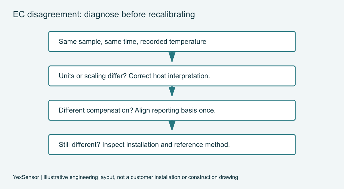
Record synchronized EC and temperature in the same stable sample. Illustration only: 1000 µS/cm raw and 909 µS/cm corrected can describe one sample under a hypothetical 30 °C, 25 °C reference, 2%/°C linear correction: 1000 / 1.10 ≈ 909. This is not a validated S1-EC algorithm or test result.
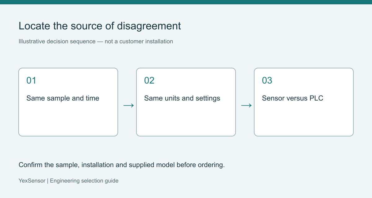
Compare units: 1 mS/cm equals 1000 µS/cm. Check for duplicate scaling and incorrect register data types before investigating compensation.
Compare temperature against a suitable reference after stabilization. Keep probes in the same sample without mechanical interference; an incorrect temperature undermines the correction.
Document compensation status, reference temperature and correction model. Ask about settings not exposed in menus; an unavailable setting does not mean compensation is absent.
A model-specific starting point for procurement
YexSensor YEX-S1-EC is a conductivity sensor family with automatic temperature compensation. The table uses the supplied manual and flags a webpage range discrepancy. Select the cell, material and range for the actual sample.
| Item | Verified specification / source | Procurement check |
|---|---|---|
| Manual range options | 0–20; 0–200; 0–5000 µS/cm; 0–200 mS/cm | Webpage instead lists 0–20 mS/cm; confirm the variant. |
| Accuracy | ±1% F.S.; temperature ±0.3 °C | Compare full-scale error with the operating threshold. |
| Working limits | 0–50 °C; pressure <0.6 MPa | Compensation does not extend these hardware limits. |
| Compensation | Automatic, Pt1000 | Confirm reference temperature and correction model. |
| Signal / supply / power | RS485 Modbus RTU; 12–24 V DC ±10%; 0.2 W at 12 V | Check loaded supply and actual data interpretation. |
| Materials | ABS / SUS316L (default) / PVC listed | Confirm actual wetted components; do not assume all-plastic construction. |
| Protection / mount / cable | IP68; 3/4 NPT; 5 m cable | Confirm cable jacket and ordered connection. |
The manual lists 0–5000 µS/cm where the webpage lists 0–20 mS/cm. These are not equivalent spans. Confirm the ordered cell and revision rather than merging the lists. The manual’s ±1% F.S. means ±50 µS/cm on a 5000 µS/cm span, not ±1% of each reading.
The manual identifies Pt1000 compensation but not a complete correction algorithm. Its Modbus example differs from the register table in the requested count; use a revision-confirmed map rather than copying request bytes.

Decide whether to change settings, installation or hardware
Change only identified configuration errors. Preserve the original settings and test the approved correction across the relevant conditions, not just one comparison point.
Review the installation when bubbles, fouling, incomplete immersion or thermal gradients are present. Cleaning and repositioning may restore a useful measurement without replacing the electronics. Follow the model's maintenance instructions; abrasive treatment or unsuitable chemicals can alter the measuring surface and create a new error.
Replace or change the measuring arrangement when the required range, chemistry, operating limits or interface cannot be supported. For samples with unusual chemistry or large composition changes, evaluate whether the compensation approach remains appropriate. A different housing alone does not solve an unsuitable correction model.
| Approach | When it fits | Decision boundary |
|---|---|---|
| Configuration correction | Identified unit or compensation mismatch | Record settings and retest across the operating interval. |
| Installation correction | Bubbles, deposits or temperature gradients | Restore representative contact before recalibration. |
| Hardware change | Range, chemistry or interface incompatibility | Confirm a replacement addresses the identified limitation. |
Three project applications
These examples describe proposed engineering approaches, not measured results from named customer sites. The acceptance criteria must be agreed for each actual process.
Industrial reuse water blending
Field challenge: inlet streams differ in both ionic content and temperature. Integration approach: record temperature alongside conductivity and validate the selected reporting basis against representative blends. User value: the integrator can distinguish a configuration mismatch from a genuine change in water composition before assigning blending limits.
Rinse-water recovery equipment
Field challenge: hot and cool batches enter the recovery system at different times. Integration approach: compare synchronized samples, define whether the diversion rule uses compensated EC and verify the sensor remains within its permitted operating temperature. User value: the OEM avoids commissioning a valve around inconsistent measurement definitions or assuming compensation permits exposure beyond hardware limits.
Cooling-water monitoring package
Field challenge: temperature and dissolved-ion concentration can change together during normal operation. Integration approach: trend both values and compare the controller's conductivity calculation with the sensor's documented output. User value: troubleshooting starts with the measurement chain rather than automatically blaming a probe when the displayed value changes during a thermal cycle.
PLC and SCADA integration: correct once, label clearly
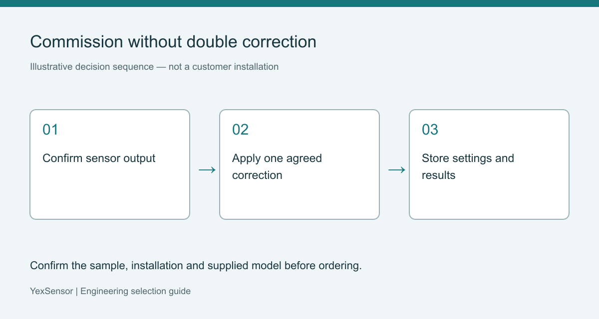
Use the supplied RS485 Modbus RTU document to configure the master and map the appropriate registers. Verify units, scaling, byte order, data types and update behavior. Where the sensor already reports compensated conductivity, applying another temperature correction in the PLC can distort the result.
If the project requires a host-side calculation, confirm that the necessary uncorrected measurement is actually available. Record the equation or lookup method, its applicable conditions and the owner of that configuration. Do not invent access to raw data because the device supports Modbus.
Store measurement quality and communication freshness alongside the process tag where the system supports them. During maintenance, prevent a disconnected instrument from appearing as a valid unchanged value. Verify the reporting label on the historian as well as the local display; commissioning is incomplete if those two systems describe different quantities.
Specify a useful acceptance test and inquiry
Agree comparison points that represent the intended temperature and conductivity conditions. Use suitable reference equipment and standards according to their instructions, recording identification, condition and uncertainty where available. A repeatable test procedure is more useful than an unexplained requirement that two instruments must show identical final digits.
For the YEX-S1-EC online conductivity sensor, provide the water composition, expected EC span, temperature excursions, existing comparison readings, compensation settings, PLC details, cable route and quantity. Include the decision the value will govern. Send Your Project Requirements to review the configuration and documentation before ordering.
Confirm accessories, packaging, delivery and service terms. Sources: official YEX-S1-EC page and the matching model User Manual, technical specifications and installation/communication sections; reviewed October 23, 2026. Unresolved fields require written confirmation.
Frequently asked questions
Q1. What does conductivity temperature compensation actually do?
It estimates conductivity at a selected reference temperature using an instrument's correction approach. It does not remove real changes in ionic composition. In an industrial monitoring project, identify the reference temperature and applicable model before comparing instruments, then document those settings in the purchase and acceptance records so the reported quantity remains consistent.
Q2. Should I always use a fixed temperature coefficient?
No. A fixed coefficient may be appropriate for a defined sample and temperature interval, but it is not a universal water property. When composition changes substantially, validate the approach against representative conditions. Ask the supplier to identify the supported correction model and its limits instead of entering a familiar coefficient without evidence.
Q3. Why can a PLC value differ from the sensor value?
The host may use incorrect units, scaling, register interpretation or an additional temperature correction. First compare the same reported quantity at the same time, using the supplied Modbus document. If the sensor already compensates conductivity, remove only an identified unintended second correction after approval, and retest the complete signal path before changing calibration.
Q4. Does automatic compensation permit hotter process water?
No. Compensation addresses a measurement relationship; it does not extend the allowed temperature of the housing, electrodes, seals or cable. For heated rinse water, specify the maximum exposure and cleaning conditions before selecting the sensor. Obtain the exact operating limits and consider sample conditioning only if it preserves the required measurement meaning.
Q5. How should I select the conductivity range?
Use the expected normal, minimum and upset values, then confirm the ordered configuration and its performance near decision thresholds. YEX-S1-EC lists several ranges, but the delivered probe and calibration must match the application. Avoid selecting solely by the largest available span, and ask whether a range change requires different hardware or factory configuration.
Q6. Is a TDS comparison enough to validate EC?
No. TDS may be calculated from conductivity using a composition-dependent factor, while an independent laboratory method measures a different quantity. To investigate temperature-related EC differences, compare conductivity units and compensation settings first. If TDS reporting is also required, validate its conversion separately and include the agreed factor and method in the project documentation.
Q7. What evidence should accompany a sensor complaint?
Provide synchronized EC and temperature readings, units, sample conditions, reference-device details, compensation settings and the current host mapping. Add observations about bubbles, deposits and recent cleaning or configuration changes. This evidence helps distinguish installation and interpretation problems from a sensor fault, reducing the risk of ordering a replacement that reproduces the same disagreement.
Q8. What should the supplier confirm before a repeat order?
Confirm model revision, selected range, wetted materials, operating limits, cable, compensation behavior and protocol compatibility with the earlier installation. Include a saved configuration and acceptance procedure in the order reference. A matching model label alone does not demonstrate that a replacement arrives with the same settings or preserves the meaning of historical conductivity data.
Q9. Can corrected EC establish that reuse water is safe?
No. Conductivity describes electrical behavior associated with dissolved ions, not every chemical or microbiological hazard. Temperature correction makes a defined EC comparison more useful but does not create a reuse approval test. Select additional monitoring and acceptance requirements for the intended reuse duty, and keep the conductivity sensor's role explicit in the project scope.
Summary
Resolve temperature-related conductivity differences by comparing the same quantity, units, sample and settings. Check the temperature measurement and host scaling before recalibration, and apply the intended compensation only once. YEX-S1-EC provides a digital conductivity option, but the ordered range, operating limits and correction behavior must be confirmed for the sample. A sound equipment package includes synchronized acceptance testing, documented configuration and a clear process decision. Send those conditions with your inquiry so product selection addresses the actual source of uncertainty rather than simply replacing the probe.


