


 Chinese
 Spanish
 French
 Russian
 German
 Portuguese
 Indonesian
 Thai
 Vietnamese
 Arabic


A cooling tower conductivity sensor replacement should start with the existing controller's input, not the probe's thread size. For treatment equipment suppliers and retrofit contractors, a successful replacement preserves a valid measurement, compatible signal interpretation and tested blowdown behavior without assuming that every conductivity probe is interchangeable.

Cooling tower conductivity sensor replacement: identify what the cabinet actually accepts
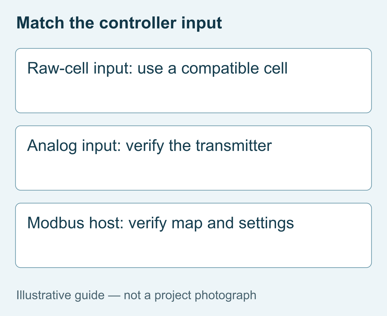
Before quoting a replacement, obtain the controller model, input diagram and original sensor code. A cabinet may expect a raw conductivity cell, a transmitter's analog signal or digital measurements. These are different interfaces. A powered RS485 probe cannot simply replace an electrode connected to a dedicated conductivity input, even when both products measure the same parameter.
Separate measurement hardware from control responsibility. The probe measures conductivity; the host interprets that value and applies the approved blowdown logic. The valve and its feedback complete the operating function. Replacing the probe does not by itself verify valve movement, prevent excessive discharge or establish the treatment program's setpoint.
The existing cooling tower conductivity monitoring guide covers the broader application. This replacement guide focuses on preserving compatibility and commissioning evidence when the cabinet, sample arrangement or sensor supplier changes.
Choose between three retrofit routes
| Input | Retrofit route | Proof needed |
|---|---|---|
| Dedicated raw-cell input | Use an electrically compatible cell or replace the measuring interface | Controller supports the cell constant, temperature element and wiring. |
| Analog transmitter input | Select a documented analog transmitter arrangement | Supply, loop wiring, engineering scale and fault handling agree. |
| PLC or gateway with Modbus master capability | Consider a powered RS485 Modbus probe | Register map, serial settings, units and invalid-data behavior are tested. |
A spare serial port is not proof of Modbus master capability. Check the installed software, available channel capacity and responsibility for the driver. If a gateway is necessary, include configuration, enclosure, power and support in the purchase scope. Otherwise the probe price understates the installed cost.
Keep a rollback arrangement for a planned outage: the original settings, wiring photographs and approved temporary operating procedure. A replacement should not depend on guessing an address or scaling factor while the process is waiting to restart. Do not perform exploratory writes on a live control loop.

YEX-S1-EC specifications and their purchasing consequences
The YexSensor YEX-S1-EC conductivity sensor is a candidate for a compatible RS485 installation. The specifications below follow its user manual, page 4. They do not establish interchangeability with a raw cell or suitability for every cooling-water chemistry.
| Parameter | YEX-S1-EC | Buyer check |
|---|---|---|
| Measuring range options | 0–20, 0–200, 0–5000 µS/cm; 0–200 mS/cm | Select for normal operation and excursions, not cabinet display capacity. |
| Accuracy | ±1% F.S.; temperature ±0.3°C | Assess absolute error near the operating decision. |
| Interface and supply | RS485 Modbus RTU; 12–24 V DC ±10% | Confirm a compatible master and loaded supply at the probe. |
| Power | 0.2 W at 12 V | Include the probe in the cabinet supply budget. |
| Working limits | 0–50°C; pressure below 0.6 MPa | Check the sample and complete fitting assembly. |
| Wetted materials | ABS/SUS316L (default)/PVC | Specify the configuration against chemistry and cleaning exposure. |
| Installation and protection | Immersion; 3/4 NPT; IP68 | Validate mounting and access; IP68 is not a pressure rating. |
| Cable and compensation | Standard 5 m, customizable; Pt1000 automatic compensation | Specify route and length, and align the temperature basis. |
Full-scale accuracy matters when selecting a replacement. For the 0–5000 µS/cm option, 1% of full scale is 50 µS/cm. For 0–200 mS/cm, it is 2 mS/cm. These calculations explain the specification; they are not estimates of total installed uncertainty or proof that either span suits your control requirement.
Compare that absolute error with the project's required decision margin. Do not buy a much wider span solely because it covers every possible future project. Equally, do not choose a narrow span that saturates during a credible excursion. Record normal, minimum and upset values in the instrument schedule.
Inspect the sample location before changing the sensor
A replacement can reproduce the old installation's error. Water beside a makeup inlet or chemical injection point may not represent the controlled circuit. A stagnant branch can display a stable value after circulation has stopped. Identify the intended measuring location and verify that it receives representative water during the relevant operating states.
For a bypass, examine isolation valves, available pressure, actual sample delivery and the outlet destination. For immersion, examine changing water levels, deposits, orientation and retrieval access. Neither arrangement is universally preferable. The flow-through versus immersion comparison helps define that installation boundary.
Check the temperature at the sensor rather than relying on a nominal tower operating temperature. Sample cooling can change the comparison basis. Align compensation settings when comparing instruments, and do not recalibrate a correctly operating probe to conceal differences in reference temperature or compensation method.

Apply the replacement strategy to three project situations
Legacy blowdown controller with a proprietary probe input
The challenge is electrical compatibility, not merely a worn sensor. Review the controller's approved cell requirements before selecting a replacement. A digital probe may require a separate host or controller upgrade. The value is avoiding a purchase that fits mechanically but cannot produce a usable input for the existing cabinet.
Packaged cooling-water skid with an existing PLC
The challenge is integrating another device without copying an unrelated register map. Assign the new probe its own tag, serial settings and decoding definition. Verify conductivity, temperature and fault indication against the commissioning record. The value is a repeatable OEM configuration that can be supported across subsequent equipment deliveries.
Industrial loop with changing sample conditions
The challenge is deciding whether an unstable reading comes from the probe or the sample. Record flow, temperature and process events before replacement. Improve the sample arrangement where necessary, then verify the selected sensor within its limits. The value is resolving the cause instead of repeatedly replacing serviceable instruments. These are illustrative project situations, not customer performance claims.
Commission the signal and blowdown response separately
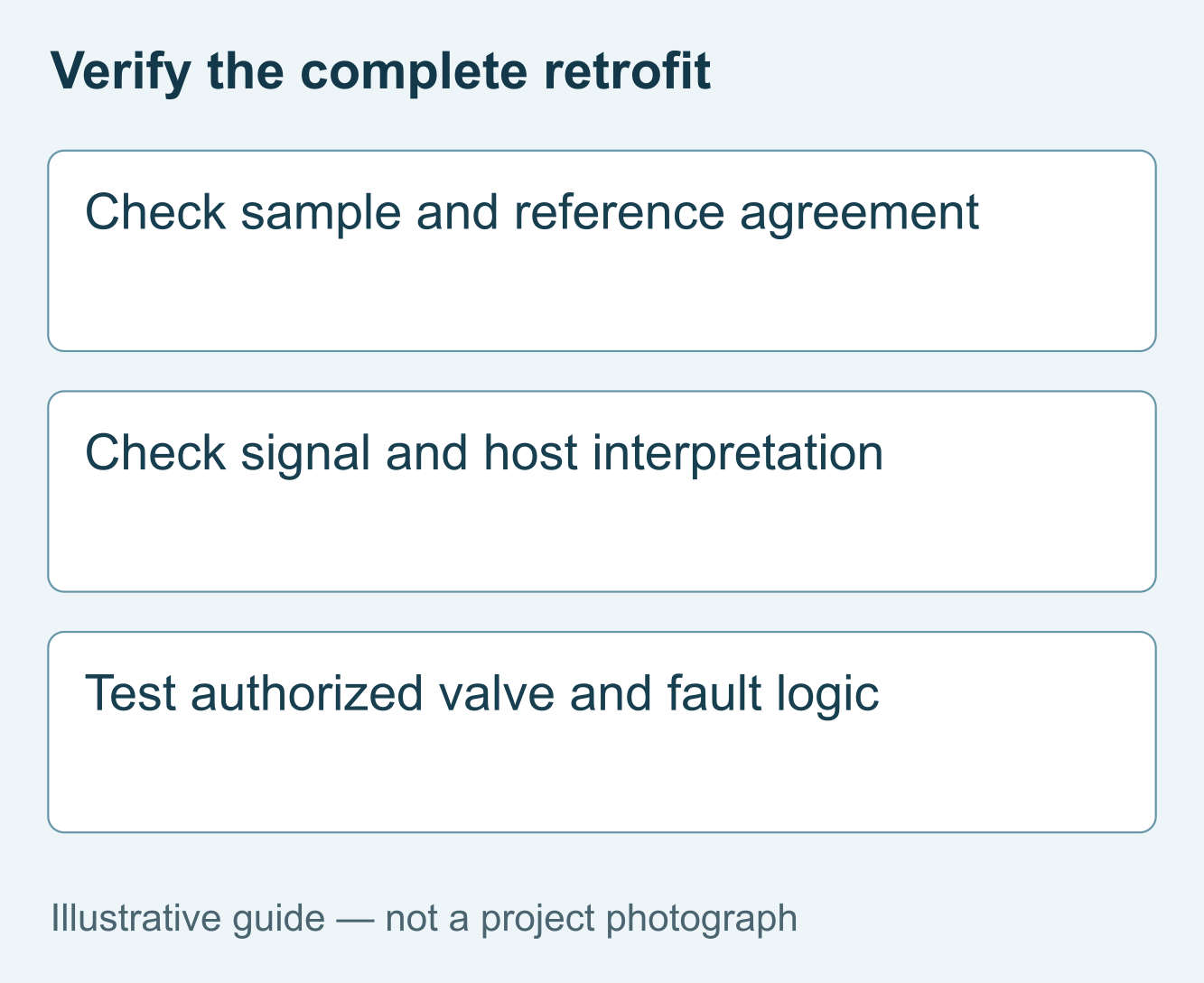
First prove the measurement chain with approved reference checks. Compare the same sample, units and temperature basis. Then compare the digital response, PLC value and operator display. If communication fails, use the RS485 troubleshooting sequence before changing calibration or purchasing another sensor.
Next test the control response under the project's authorized procedure. Confirm the intended action for stale data, loss of communication and maintenance mode. Verify valve operation separately. A host that receives a number successfully has not necessarily demonstrated a valid sample or a functioning discharge path.
Retain a before-and-after record containing the old and new model numbers, configuration, reference results and approved logic changes. Agree the observation period and operating transitions in advance. Acceptance should establish reproducibility, not merely one successful reading at the end of installation.
Procurement scope and project configuration review
Compare complete offers: probe, mounting or cell, cable, interface hardware, driver work, reference checks and commissioning support. Ask who handles warranty diagnosis when the probe and controller come from different suppliers. Confirm delivery, packing, spare parts and any custom configuration in the written quotation.
For a YEX-S1-EC configuration review, provide the existing controller and probe codes, water chemistry, expected conductivity, temperature, pressure, input type, cable route, quantity and delivery destination. Include wiring photographs and the proposed control scope. Send Your Project Requirements so the replacement can be evaluated as an installed measuring point.
Frequently asked questions
Q1. Is a cooling tower conductivity sensor replacement normally plug-and-play?
Only when the electrical interface, measuring configuration and installation match the existing system. A common thread does not establish compatibility with a controller's cell input or register map. For a retrofit, send the old probe code and cabinet documentation before ordering. Ask the supplier to identify which parts can remain and which require modification.
Q2. Can an RS485 probe connect directly to a raw conductivity input?
No. A powered digital probe and a raw cell provide different signals. The receiving equipment must support the proposed interface and interpret its data correctly. Where the existing cabinet only accepts a particular cell, retain a compatible measuring arrangement or include an approved interface upgrade. Price and validate that work before comparing replacement quotations.
Q3. Why does the replacement disagree with the handheld meter?
Differences may come from sample location, temperature compensation, units, calibration or measurement performance. Compare the same water at closely matched times and document the temperature basis before adjusting either instrument. If the PLC differs from the sensor response, investigate decoding separately. Ask for acceptance evidence that distinguishes sample disagreement from an electrical or software error.
Q4. Should I choose the widest available conductivity range?
Not by default. A full-scale accuracy specification creates a larger absolute error on a wider span, while an undersized range can saturate during excursions. Select the range against normal values, credible peaks and the required decision margin. Include those values in the procurement schedule rather than asking only for the highest available measuring range.
Q5. When is YEX-S1-EC a suitable candidate?
Consider it when RS485 Modbus RTU suits the host and the selected range, materials and installation remain within its manual limits. Its documented working temperature is 0–50°C and pressure is below 0.6 MPa. Review the complete assembly and water chemistry before purchase; the sensor's individual rating does not approve every fitting or sample panel.
Q6. Does stainless steel automatically make the replacement suitable for seawater?
No. Suitability depends on the exact alloy, other wetted components, temperature, deposits and cleaning exposure. Do not select a series merely because its housing looks metallic. Provide the actual water chemistry and required service conditions, then specify an assessed material configuration. A generic cooling-water application label is not evidence of seawater compatibility for a particular assembly.
Q7. What should the supplier include in a retrofit quotation?
Request the exact sensor configuration, mounting, cable, interface hardware, documentation and commissioning responsibilities. Identify whether PLC programming, valve testing and site reference comparisons are included. State quantity, destination and required date. This separates a probe-only price from an operational replacement package and makes the responsibility for troubleshooting after installation clear to both parties.
Q8. What should be tested before returning automatic control to service?
Verify the installed measurement, host interpretation, communication loss, recovery and authorized control response. Confirm the valve and sample delivery independently. Retain the tested settings and reference results with the equipment tag. The project engineer should define acceptance criteria and release authority; a supplier's communication demonstration alone does not authorize automatic blowdown under every operating condition.
Q9. Can cable length or accessories be customized?
The YEX-S1-EC manual lists a standard 5 m cable and customizable lengths. Specify the actual route, termination and environmental exposure rather than ordering by straight-line distance alone. Confirm the resulting configuration, documentation and delivery in the quotation. Custom cabling does not remove the need to check supply voltage, communication reliability and protection at field joints.
Summary
Select a cooling-tower replacement by the existing input, required measuring performance and actual sample conditions. YEX-S1-EC is a digital conductivity candidate, not an automatic substitute for a raw cell or a complete blowdown controller. Match range, materials and manual limits, then verify sampling, signal interpretation and control behavior separately. A useful inquiry includes the original equipment codes, wiring, water conditions and supply boundary. That information lets an integrator compare an appropriate probe replacement with a justified interface upgrade before committing to installation.


