


 Chinese
 Spanish
 French
 Russian
 German
 Portuguese
 Indonesian
 Thai
 Vietnamese
 Arabic


Water quality monitoring panel design must separate representative sampling, sensor performance, and host integration. For filtration and utility-water panels using turbidity and optional conductivity, define those responsibilities before choosing probes. Otherwise, a complete-looking package can leave the integrator responsible for unpriced sampling and commissioning work.
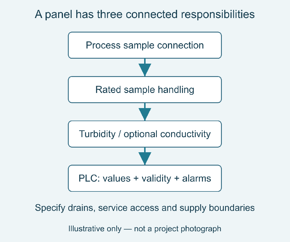
Water quality monitoring panel design begins with the delivery boundary
An equipment list is not a complete scope. A supplier may quote probes and mounting hardware while the contractor expects isolation valves, sample conditioning, a controller, and documented acceptance tests. Both parties can believe they agreed on a monitoring panel while pricing different systems.
Write the boundary around process connection, sample discharge, electrical supply, and host interface. Assign responsibility for tubing, fittings, drainage, protection, communications programming, calibration materials, and site verification. Include the conditions that must already exist at the site for the package to operate as intended.
The resulting document should answer what is supplied, what is configured, what is tested, and what remains the installer's responsibility. This is especially important for distributors assembling equipment from several manufacturers. A shared communication protocol does not establish mechanical compatibility or a shared warranty for the assembled system.
Specify the sample path independently of the sensors
A probe only measures the water reaching its active surface. Define the source point, minimum and maximum operating conditions, expected solids, chemicals, and the reason each parameter is needed. Include start-up, shutdown, and cleaning conditions, not only the normal operating value used in the initial enquiry.
Document pressure reduction, flow control, drainage, and any conditioning devices as separate components. Their ratings and effects on the sample must be suitable for the measurement objective. IP68 describes an ingress-protection classification; it does not establish the pressure capability or chemical compatibility of the complete panel.
| Design responsibility | Deliverable to specify | Failure avoided |
|---|---|---|
| Sample acquisition | Source location and representative routing | Measuring water unrelated to the control decision |
| Sample handling | Rated fittings, intended conditions, drainage | Unsafe or unrepresentative chamber operation |
| Measurement | Model-specific performance and maintenance plan | Selecting by range or appearance alone |
| Data delivery | Register map, units, validity, fault behavior | A plausible but incorrectly interpreted host value |
| Acceptance | Separate factory and site test procedures | Confusing signal testing with process validation |
Choose series by duty, not by a standard panel photograph
For a digital turbidity point with practical manual service access, consider the YEX-S1-TS. Where optical deposits justify automatic wiping, assess the YEX-S2-ZS-8S brush-equipped sensor. Its optional analog configuration may suit a different host requirement; confirm the delivered version rather than assuming every S2 unit provides both interfaces.
Add conductivity only when changes in ionic content answer a project question. The YEX-S1-EC Modbus conductivity version is a separate measurement choice, not an automatic companion needed to make a turbidity panel complete. Conductivity does not identify individual contaminants or establish particulate removal.
| Model-specific fact | Documented value | Design implication |
|---|---|---|
| YEX-S1-TS communication | RS485 Modbus RTU | Allocate an address and verified host mapping |
| YEX-S2-ZS-8S communication | RS485 Modbus RTU; optional 4–20 mA | State the ordered interface in the bill of materials |
| YEX-S1-EC Modbus version range | 0–5000 μS/cm | Compare the exact variant with expected conductivity |
| These three models' supply | 12–24 V DC | Calculate the complete panel supply separately |
| S2 temperature and pressure | 0–60°C; below 0.2 MPa | Check supply conditions and transients |
| S2 stated consumption | 0.2 W at 12 V | Not a complete panel or startup power budget |
| S2 housing and cable | ABS + 316L; 5 m cable | Assess chemistry and route length separately |
| These three models' protection | IP68 | Rate connectors and assemblies separately |
Attach the exact configuration datasheet to the purchase specification. S2 figures above follow its manual; cable length does not identify sheath material. For aggressive samples, obtain the cable-material declaration. Size the supply for sensors, brush operation, valves, controller and gateway, including documented peak demand.

Compare serial and parallel measurement branches
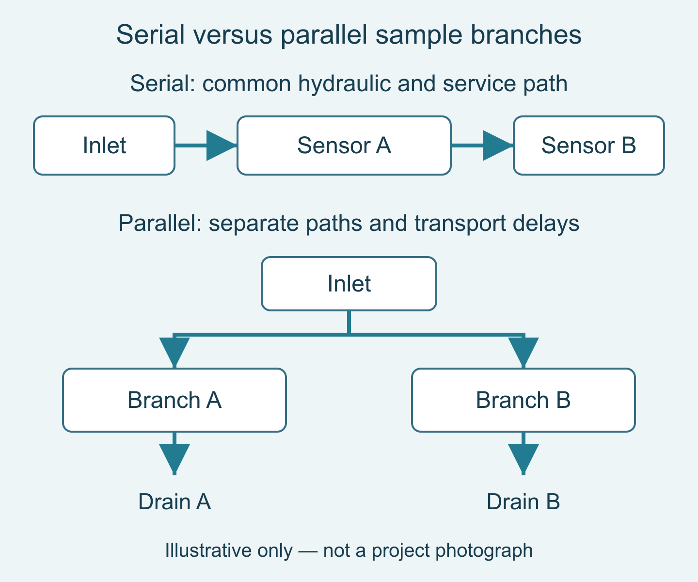
A serial path can reduce tubing and connections, but every upstream component can affect downstream pressure, residence time, and servicing. Assess whether cleaning or isolating one instrument interrupts all measurements. Do not route chemically altered sample water through another measurement without evaluating the effect on that parameter.
Parallel branches allow more independent servicing and operating conditions, but introduce separate flow paths and potentially different delays. Define how each branch is identified and verified. A shared inlet does not guarantee that all instruments report the same instant of process water at the host.
For an illustrative branch holding 0.5 L at 1 L/min, nominal transport time V/Q is 0.5 min, or 30 seconds. This is a design example, not a recommended flow or sensor response specification. Mixing, instrument response and controller processing add effects requiring site verification.
Three panel applications with different priorities
OEM filtration and reuse skids
The challenge is a repeatable package that still suits varying water and installation conditions. Use a standard electrical architecture with project-specific sample interfaces and documented option limits. The value is controlled customization: the OEM can reuse drawings and host mapping without assuming identical materials, cleaning requirements, or acceptance thresholds for every customer.
Industrial utility-water retrofit projects
The challenge is compatibility with existing cabinets and host input capacity. Check whether the system needs Modbus, analog inputs, or a gateway, and establish who configures each link. The value is fewer commissioning surprises and a clear distinction between sensor functionality and additional integration hardware that the site must purchase.
Distributed monitoring stations supplied through distributors
The challenge is maintenance by teams that did not build the panel. Provide labeled branches, accessible service points, exact spare-part identification, and usable instructions. The value is repeatable support across installations. A layout that allows safe sensor removal and fault isolation can matter more than reducing the enclosure size by a small amount.
Make the host integration contract explicit
For RS485 Modbus RTU, record addresses, baud rate, parity, register functions, data type, scaling, units, and byte order. Specify polling and timeouts against the device documentation. Use the RS485 communication troubleshooting guide for connection faults; shared brands or protocol names do not establish identical register maps.
The host should distinguish current valid measurements from communication failures and maintenance states. Decide whether it stores raw values, compensated values, temperature, and diagnostic information where supported. For conductivity, identify the reporting temperature basis and compensation setting so comparisons are not made between unlike values.
Analog integration has its own checks. Verify the ordered output, configured measurement span, receiving input, wiring requirements, and failure interpretation. A correct electrical span does not prove the water measurement is correct. Maintain separate acceptance records for signal transfer and measurement performance.
Plan maintenance access and acceptance before fabrication
Leave space to remove probes and service any brush or chamber without dismantling unrelated equipment. Route cables so servicing does not strain connectors. Review labels, drain access, and the ability to isolate a branch safely. Verify wetted-material suitability for the actual chemicals and salinity; a stainless appearance is not evidence of seawater suitability.
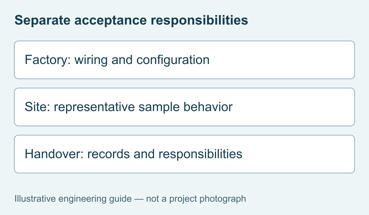
Factory acceptance should prove wiring, tag mapping, alarms and fault handling. Site acceptance should prove representative sampling and measurement performance. Require separate records for simulated signals and water comparisons, so shipment approval does not substitute for commissioning under actual operating conditions.
Request a panel quotation with defined interfaces
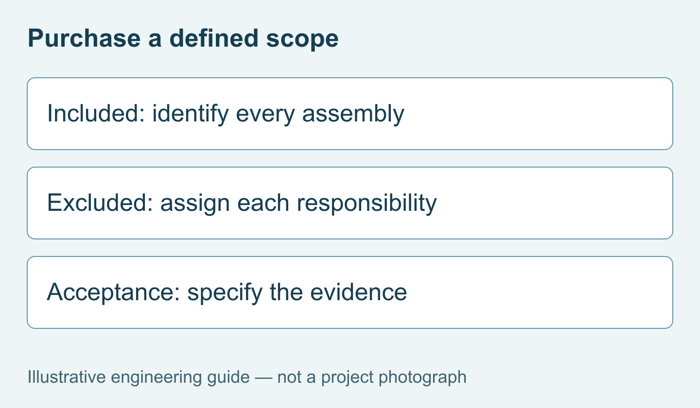
Provide the process drawing, required parameters, operating envelope, sample connections, drainage arrangement, host details, available power, service access, quantity, and delivery destination. Identify who supplies chambers, valves, controller, calibration materials, and installation. Review the YEX-S1-EC digital option where conductivity is relevant, then Send Your Project Requirements. Request model-specific documentation and a quotation with explicit inclusions and exclusions.
FAQ
Q1. What should a water quality monitoring panel design include?
It should define sampling, measurement, data delivery, maintenance, and acceptance responsibilities. List the process and electrical interfaces as well as the instruments. For water quality monitoring panel design, the practical purchasing question is what the supplied assembly can do under the stated site conditions, not simply how many parameters appear on its equipment list.
Q2. Does RS485 Modbus RTU make all sensors interchangeable?
No. The shared interface does not standardize measurement performance, register maps, data types, units, or installation limits. Verify the exact delivered documentation and test host interpretation for each model. Procurement should include configuration and integration requirements explicitly so replacing a probe does not unexpectedly require different wiring, revised controller code, or a changed acceptance procedure.
Q3. Does an IP68 sensor make the panel pressure-rated?
No. The sensor's ingress-protection designation does not certify the complete sampling assembly for process pressure. Chambers, tubing, glands, valves, and connections each require appropriate selection. State the expected operating and transient conditions, and obtain the relevant component ratings. Never infer assembly suitability from an enclosure label or from the appearance of a submerged product photograph.
Q4. When should a panel use parallel sample branches?
Consider parallel branches when instruments need independent servicing or different approved sampling conditions. Account for branch identification, flow verification, and different transport delays. Serial arrangements may be simpler but couple maintenance and hydraulic behavior. Select the architecture after reviewing measurement interactions and access, rather than choosing the layout that uses the fewest fittings on a drawing.
Q5. Should every filtration panel include conductivity measurement?
No. Include conductivity when ionic changes inform a defined operational decision, such as source blending or investigation of unexpected dissolved-content changes. It cannot replace turbidity for particle-related monitoring. Ask the customer what action each parameter supports, then specify the relevant sensor variant and reporting basis. Additional instruments without a decision purpose increase servicing and integration work.
Q6. Is a brush-equipped turbidity sensor always preferable?
No. A brush is valuable where deposits create a documented maintenance burden, but it adds its own service considerations and does not solve poor sampling. Compare the S2 option with an accessible S1 installation using actual fouling conditions and maintenance resources. Confirm optical performance separately; cleaning capability is not evidence of suitability for every low-level acceptance requirement.
Q7. How can distributors prevent gaps between component warranties?
Define the supplier for each component and the party responsible for assembly, configuration, and site commissioning. Request written warranty terms and exclusions rather than assuming one sensor warranty covers the complete panel. Include support documentation and replacement identification in the order. A clear responsibility matrix helps route faults without promising commercial terms that have not been agreed.
Q8. What should factory acceptance prove before shipment?
It should prove the functions explicitly included in the factory test scope, such as wiring, configuration, communications, alarms, and simulated fault handling. Document water-test conditions where relevant. It cannot automatically reproduce the site's sampling behavior. Require a separate site procedure for representative sampling and measurement comparison so shipment approval does not erase unresolved field verification tasks.
Q9. What determines the cost beyond the sensor price?
Sampling hardware, isolation, enclosure requirements, controller functions, interface conversion, assembly, testing, documentation, and service access all affect the package. State these requirements before comparing quotations. Ask suppliers to identify optional and excluded items, delivery conditions, and spare parts separately. This makes a lower initial component price distinguishable from a lower cost for the complete required system.
Summary
Specify a monitoring panel as connected responsibilities, not a collection of probes. Representative sampling, model-specific performance, reliable host interpretation, and service access all determine whether the package supports the customer's decision. Select S1, S2, and conductivity options only where their verified capabilities match the duty. Separate sensor protection from assembly ratings and factory signal checks from site measurement validation. A clear quotation should identify operating conditions, interfaces, included hardware, responsibilities, acceptance procedures, and commercial boundaries before fabrication begins.


