


 Chinese
 Spanish
 French
 Russian
 German
 Portuguese
 Indonesian
 Thai
 Vietnamese
 Arabic


An inlet reading cannot describe every incubation tray
Fish egg incubation dissolved oxygen monitoring should distinguish the quality of incoming water from oxygen conditions after water passes through the incubation system. An inlet sensor provides a useful supply reference. Add an outlet or zone measurement when the project must detect oxygen depletion, unequal flow or a local problem that an inlet measurement could miss.
For hatchery equipment manufacturers, the purchasing decision is therefore about coverage as much as probe performance. Select the number and position of channels from the hydraulic layout, egg loading and consequences of a missed event. A single convenient location is not automatically a representative one.
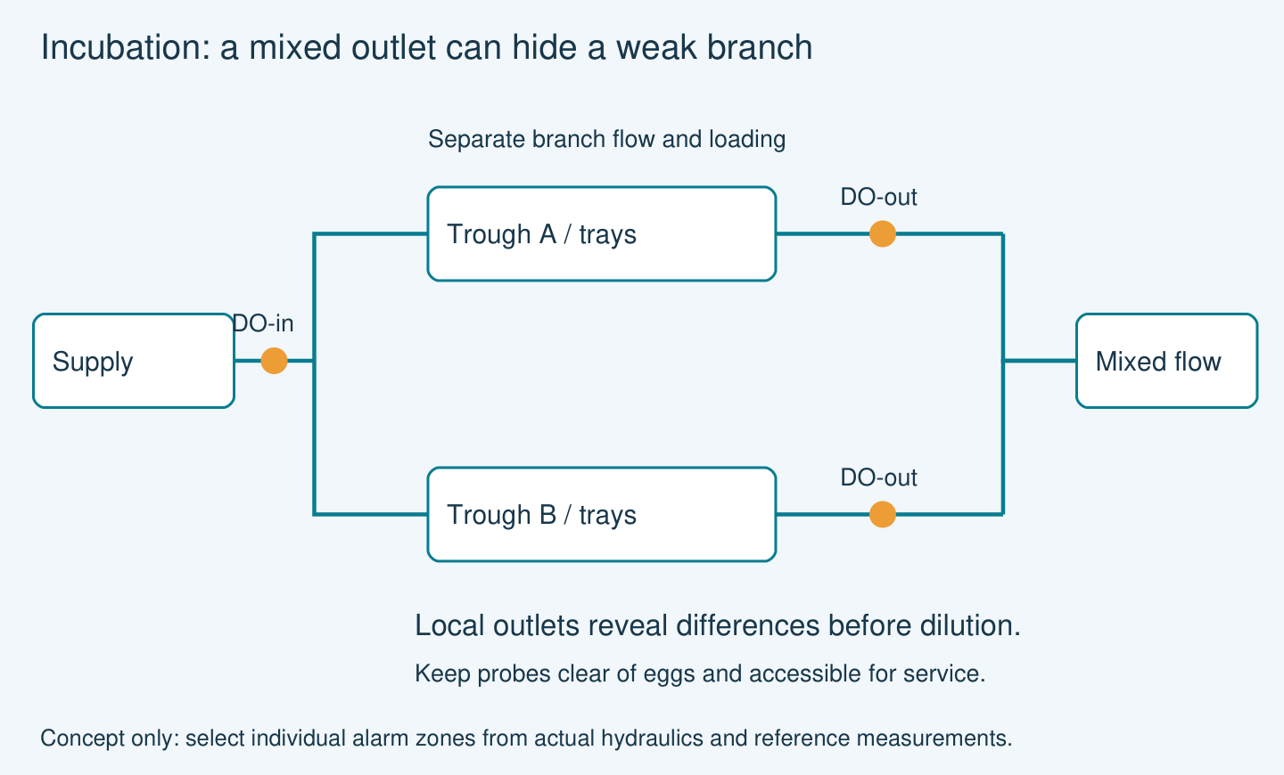
The risk hidden by a common outlet
Water from several parallel troughs may mix before reaching a shared outlet probe. A healthy branch can dilute the signal from a poorly supplied branch. A normal mixed reading therefore does not prove that every tray has adequate oxygen.
FAO incubation guidance describes how water movement must supply oxygen while avoiding excessive disturbance of eggs, and how requirements change with development. This supports checking distribution and stage-specific conditions rather than choosing a universal DO alarm for all fish species. Verify the proposed monitoring coverage against the actual trough hydraulics and stage-specific requirements.
Match the DO probe to the measuring location
The official YEX-S1-RDO product page identifies optical fluorescence measurement, a 0–20.00 mg/L range, RS485 Modbus RTU output and IP68 protection. These facts support evaluating it as an online DO channel; they do not establish that a particular trough has room for the probe or that its complete alarm chain responds quickly enough.
Use the exact model manual and drawing to confirm dimensions, mounting, temperature limits, accuracy, response and cap service before procurement. Do not substitute the specifications of S1 PRO or S2 models. Specify the required accuracy at the operating DO level and the maximum acceptable detection delay, then confirm both against the selected configuration.
Product reference: YEX-S1-RDO specifications and integration information.
Specification boundaries for the quotation
| Check | Evidence boundary | Purchase implication |
|---|---|---|
| DO range | 0–20 mg/L | Compare the hatchery operating band with this span; biological alarm limits remain species- and stage-specific. |
| Working conditions | 0–45°C; pressure below 0.2 MPa | Check the complete monitoring exposure, including cleaning; these limits do not establish egg suitability. |
| Output and supply | RS485 Modbus RTU; 12–24 V | Specify controller inputs, power and waterproof cable termination separately. |
| Installation and service | Immersion mounting; replaceable fluorescent cap | Confirm the drawing against tray clearance and provide removal access; include cap service and calibration in maintenance planning. |

Choose the layout according to the blind spot
Start by drawing every inlet, branch valve, tray path and outlet. Identify which branches share water and which operate independently. Then decide which failure must produce a separate alarm. A common supply point and selected critical outlets may be a useful starting architecture, but their coverage needs commissioning evidence.
Use temporary reference measurements across the remaining zones to test the assumption that a selected outlet represents them. If flow, loading or temperature differs materially, add a separate channel rather than averaging away the difference.
| Arrangement | Question answered | Purchase decision |
|---|---|---|
| Common inlet | Incoming supply condition | Use as a reference; do not claim individual tray coverage. |
| One trough outlet | Local downstream condition | Choose a representative flowing location and verify it against tray checks. |
| Mixed common outlet | Combined discharge trend | Accept only when dilution of a weak branch is an understood limitation. |
| Inlet plus critical zone outlets | Supply and local deviations | Budget separate channels for independently operating or unequal branches. |
Field scenarios: supply change, branch restriction and loading
If the inlet and several outlets decline together, investigate the incoming supply and oxygenation arrangement. Retain temperature and flow records so that the response is based on the process condition rather than one isolated number.
If only one outlet declines, check its valve position, blockage, tray distribution and egg loading. A stable inlet does not invalidate that local warning. Compare a reference measurement at the same location before treating it as sensor drift.
As development progresses or loading changes, repeat the coverage check. A position that was representative earlier may no longer identify the most demanding operating condition. Record the stage and loading with alarm reviews rather than silently applying the previous batch’s settings.
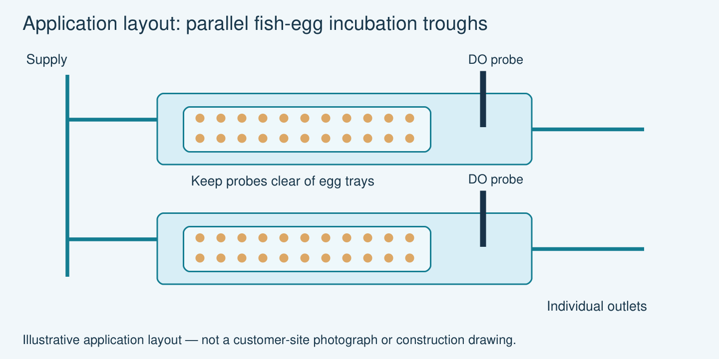
Install where the water is representative and the probe is serviceable
Place the sensing surface in continuously wetted, moving water without obstructing the intended tray flow. Do not allow the probe or support to contact eggs. Keep sufficient clearance for removal, cleaning and inspection without moving loaded trays unnecessarily.
Avoid measuring directly in an oxygen injection plume or where bubbles collect on the sensing surface. Such a location may describe the local dosing zone instead of the water reaching the eggs. Verify inlet and outlet sample positions with the hatchery designer.
Specify independent data freshness and communications-fault indications. An unchanged display must not be interpreted as proof that the sensor is still updating. Record temperature, flow status and any oxygenation equipment state alongside DO.
Test the complete chain from a representative input change through logging, alarm delivery and operator acknowledgement. Perform functional tests without deliberately exposing eggs to low oxygen. Agree the fallback procedure for sensor cleaning, power loss and failed communications before operation.
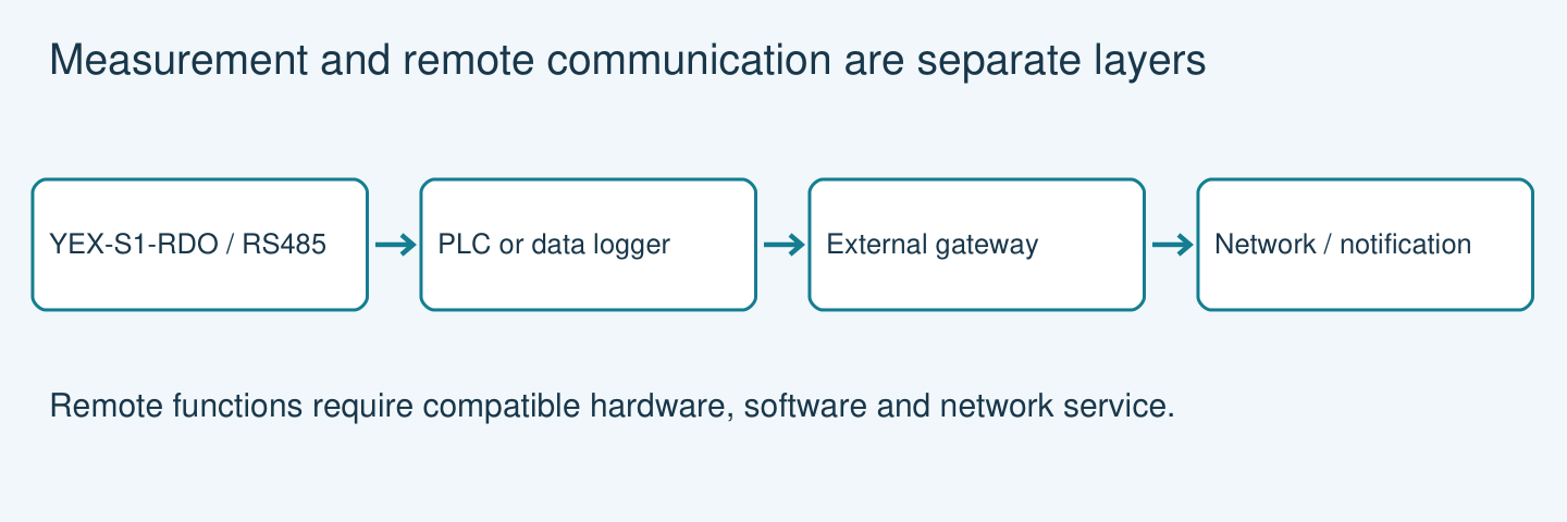
The YEX-S1-RDO provides a measurement signal over RS485 Modbus RTU. A compatible PLC or data logger reads the signal and implements the approved monitoring logic. Remote notifications require a separately specified gateway, network service and software; they are not inherent features of the probe.
Review the water quality sensor range when specifying additional hatchery measurements. Keep each channel tied to a defined operating decision and a separate acceptance requirement.
RFQ checklist for hatchery equipment buyers
Send the species, developmental stages, loading range, trough or jar drawings, water depth, branch arrangement, inlet and outlet flow, temperature range, oxygenation method and required channel count. Identify the locations needing individual alarms and the available maintenance access.
Request the exact probe dimensions, mounting assembly, current manual, register map, calibration procedure and spare-cap details. Ask the supplier to separate sensor supply from installation hardware and controller programming. The hatchery operator should approve biological alarm limits and response procedures; these are not supplied by a generic sensor range.
Technical references
Discuss Your Project Requirements
Send the project data listed in the RFQ checklist above, together with your quantity, destination, installation drawing and acceptance requirements. Identify any mandatory documentation and the decision the measurement must support.
Review the YEX-S1-RDO product information and request confirmation of the exact configuration.
FAQ
Q1. What is the correct DO alarm for fish eggs?
It depends on species, stage, temperature and hatchery practice. Obtain the operating limit from the responsible hatchery specialist and confirm the measurement basis. The sensor measuring span is not a biological safety specification and should not be used to invent a universal setpoint.
Q2. Why can inlet DO be normal while outlet DO falls?
Water changes as it moves through the loaded incubation system, and local flow can be uneven. Compare branch flow, loading and temperature before diagnosing the sensor. A paired measurement can help distinguish a supply change from a downstream issue.
Q3. Can the probe sit beside an oxygen diffuser?
Avoid assuming that this position is representative. Bubbles and a concentrated dosing plume can make the location unsuitable for evaluating water reaching the eggs. Confirm a mixed, representative measuring position with the equipment designer and verify it in operation.
Q4. When is one outlet channel insufficient?
It is insufficient when independent branches or unequal loading create important unobserved conditions. A combined outlet can hide a weak branch. Use a coverage survey to decide where separate channels are necessary and include the extra inputs in the controller quotation.
Q5. Is YEX-S1-RDO small enough for a tray?
That must be checked against the current drawing and actual tray clearances. The product category alone cannot answer it. Provide dimensions and maintenance access in the RFQ, and require confirmation that the mounting does not obstruct flow or contact eggs.
Q6. Should a portable meter replace fixed monitoring?
A portable reference is useful for surveys and verification, but intermittent checks can miss events between visits. Where continuous alarms are required, specify fixed monitoring and retain portable checks as a separate maintenance and validation tool.
Q7. What should the OEM include in its quotation request?
Include species, stage, loading, hydraulic drawings, temperature, flow, oxygenation, alarm zones and controller details. Request the exact model documentation, mounting, spare parts and commissioning scope. This avoids receiving a probe price without the hardware required to use it.
Q8. How can the alarm chain be tested safely?
Use controlled simulations and appropriate reference checks that do not expose stocked trays to harmful conditions. Verify sensor-fault handling, logging, notification and operator acknowledgement. Agree a written acceptance procedure with the hatchery before handover.
Q9. Does optical measurement eliminate maintenance?
No. The sensing surface still needs inspection and cleaning, and the optical cap requires service according to the model instructions and field condition. Budget spare parts and maintenance access; do not treat a low-maintenance measurement principle as a maintenance exemption.
Summary
Choose DO locations to reveal both supply changes and local incubation problems. YEX-S1-RDO is a candidate online channel, conditional on verified dimensions, operating limits and service arrangements. Protect representative flow, prevent bubble accumulation and test alarms without risking the eggs. An actionable RFQ includes species, stage, loading, hydraulic drawings, channel coverage and the agreed operating response.


