


 Chinese
 Spanish
 French
 Russian
 German
 Portuguese
 Indonesian
 Thai
 Vietnamese
 Arabic


pH bypass sample delay concerns transport to the measurement point, not just sensor response. Before purchasing, estimate liquid volume and flow, then verify the installed behavior. An accessible cabinet can otherwise display a representative value too late for its intended use.
Why the sampling arrangement belongs in procurement
You may choose a bypass because the main vessel is difficult to access or the direct process conditions are unsuitable for the proposed instrument. That choice transfers part of the engineering problem into the sampling line: takeoff location, transport, conditioning and drainage.
Define the sample path before ordering. A routing change can increase volume or reduce flow without changing the sensor model, making the displayed value describe an earlier process condition.
Start with the required decision: routine trending, process adjustment or a separately defined verification duty. The acceptable delay depends on that purpose. There is no universal maximum line length that makes every pH bypass suitable.
Estimate pH bypass sample delay with actual dimensions
For a completely liquid-filled line under approximately steady flow, nominal transport time is liquid volume divided by volumetric flow. Use internal diameter, not outside tube diameter. Include the wetted volume of fittings and other components between the takeoff and sensing location.
The calculation below uses an assumed 10 m tube with a 6 mm internal diameter. It excludes the flow cell, fittings and conditioning equipment. The assumed flows are neither product requirements nor validated project settings.
The calculation is a screening estimate. Mixing within components, variable flow, trapped gas and stagnant volumes can change the observed response. Verify the installed path rather than treating volume divided by flow as an exact response guarantee.
| Tube-only example | Calculation / interpretation |
|---|---|
| Assumed geometry | 10 m length; 6 mm internal diameter. |
| Internal liquid volume | V = π × (0.006 m)² × 10 m / 4 ≈ 0.283 L. |
| Assumed flow: 0.5 L/min | t = 0.283 / 0.5 ≈ 0.566 min ≈ 34 s. |
| Assumed flow: 0.1 L/min | t = 0.283 / 0.1 ≈ 2.83 min ≈ 170 s. |
| Excluded volumes | Flow cell, fittings and conditioning hardware: assess separately. |
| Result boundary | Nominal tube transport only; not tested overall system response. |
Do not confuse transport, conditioning and sensor response
Transport moves the sample. Conditioning changes the conditions presented to the instrument. The sensor then responds, and the host acquires and processes its value. These processes can interact; their published or calculated numbers should not simply be added and labelled a tested system response.
Temperature or pressure conditioning may be necessary for equipment compatibility, but it can also affect the sample being measured. Define whether the measurement represents conditioned liquid or an intended process state. Do not silently present those as interchangeable.
Emerson's analytical-measurement article explains transport delay as volume divided by flow. Its engineering discussion does not establish YexSensor product limits. See the analytical-measurement discussion of transport delay.
Use the sensor specifications as design constraints
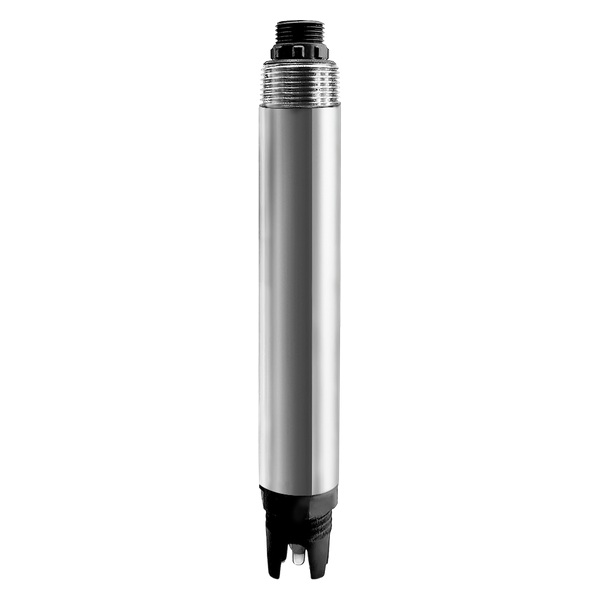
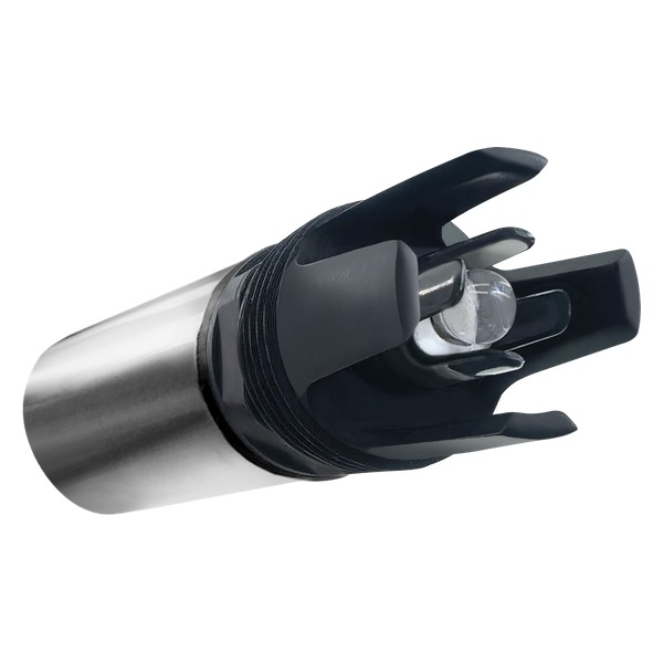
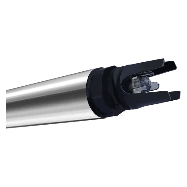
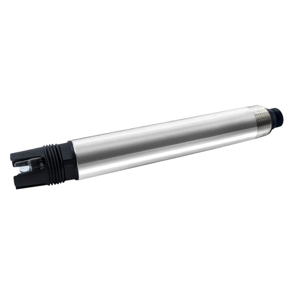
YEX-S1PRO-PH is a possible measurement element only when the liquid at the sensor and the mechanical arrangement meet its conditions. The following limits are not a specification for the flow cell, tubing, valves or cooling equipment. Those components require their own ratings and compatibility checks.
| Item | Model-specific information | Project check |
|---|---|---|
| Model and range | YEX-S1PRO-PH; 0–14.00 pH | Confirm the liquid reaching the sensor is within the approved duty. |
| Resolution and accuracy | 0.01 pH; ±0.1 pH; temperature ±0.1°C | Compare reference samples under aligned conditions. |
| Response | 10 s; response convention not specified | Assess hydraulic transport separately. |
| Supply and consumption | 12–24 VDC; 0.4 W | Include the instrument in the power budget. |
| Output | RS485 (Modbus); 4–20 mA optional | Confirm the ordered configuration and interface document. |
| Environment | 0–50°C, non-freezing; pressure <0.2 MPa | Apply limits at the probe, not only at the takeoff. |
| Housing and protection | 316L + ABS; IP68 | Check chemical compatibility and connector protection separately. |
| Cable | 5 m four-core shielded cable | Confirm length and supplied termination; jacket material is not specified. |
| Mounting | NPT 3/4; immersion arrangement | Check geometry and orientation against the manual. |
| Temperature compensation | Automatic | Do not treat differently conditioned samples as identical. |
Review the YEX-S1PRO-PH online pH sensor and its current application requirements before specifying the final configuration.
Compare three ways to arrange the measurement
Direct immersion removes the external sample-line volume but still depends on process mixing, liquid level and safe retrieval. It is worth considering where the tank is accessible and the conditions suit the sensor. The existing installation comparison can help evaluate that broader choice. Compare immersion and flow-cell installation.
A short local bypass can improve access while keeping the sample route compact. It still needs a representative takeoff, controlled flow, drainage and a mounting arrangement that keeps the electrode correctly wetted. Shorter tubing alone does not resolve a stagnant flow cell.
A remote conditioned cabinet may serve a genuine access or exposure requirement. Accept its additional components only with a clear responsibility for flow verification, conditioning and service. Do not select the remote location simply because spare wall space is available.
Make the purchasing specification measurable
Request the proposed routing, tube internal diameter, component volumes where available and operating flow range. Ask how flow is observed and what happens when it stops. A bypass that silently stalls can retain a plausible pH reading from old liquid.
Specify which components are included: takeoff, isolation, conditioning where needed, measurement chamber, drain or return connection, supports and sensor mounting. The supplier of the probe should not be assumed to supply or approve the entire assembly.
Confirm maintenance access and the method of isolation before equipment is removed. Increasing flow to reduce delay is not an unrestricted solution: hydraulic conditions, component ratings, sample consumption and the electrode installation all need review.
Illustrative arrangements that need different decisions
For a compact neutralization skid, a nearby accessible mounting location may permit a short sampling route. The engineering task is to verify that the takeoff represents the intended liquid and that the sample continues to move across operating states. The value is predictable measurement context, not merely a tidy cabinet.
For a distant instrument room, compare local and remote measurement before ordering. Include service access, signal transmission and transport time, not just tubing cost.
For an intermittent batch system, the bypass may stop between operations. Define how the host identifies unavailable or unrepresentative measurements and how the sample path is re-established. A continuously displayed number is not proof that a fresh sample has reached the sensor.
Verify the installed path before relying on its trend
At commissioning, document actual routing and flow rather than relying only on the quotation drawing. Observe a suitable process change under an approved procedure and record the takeoff context, sensor response and host timestamps. Do not introduce chemicals into an operating plant solely to create a demonstration.
When comparing a reference sample, align the conditions and the time represented by the liquid. A current tank sample and a delayed bypass reading may disagree even when neither instrument is defective. Record temperature and handling as well as the pH results.
Repeat verification after tubing, flow or conditioning changes, even when the sensor configuration remains unchanged.
Keep the quotation focused on the unresolved boundary
Identify whether you need a sensor for an approved sample path or further sampling-system design. A probe quotation does not establish responsibility for the entire assembly.
Provide the intended use of the reading, takeoff conditions, routing dimensions, expected flow and host interface. Agree on the evidence required at site acceptance and the party responsible for it. Accessories, packaging, commissioning and after-sales scope should be confirmed in the project offer rather than inferred from an instrument photograph.
Use the measurement-package guide to assign supply responsibilities and the dosing-fluctuation checks to investigate unstable trends.
Discuss Your Measurement Requirement
For a bypass sensor review, provide the takeoff conditions, proposed routing, expected sample flow, mounting arrangement and host interface.
Review the YEX-S1PRO-PH product configuration and Send Your Project Requirements for a project-specific discussion.
FAQ
Q1. How do I estimate pH bypass sample delay?
For an approximately steady, liquid-filled line, divide the liquid volume between takeoff and measurement by volumetric flow. Include relevant component volumes and use consistent units. This gives a nominal transport estimate, not a complete system response. Ask the package supplier to document dimensions and verify actual operating flow before accepting the arrangement.
Q2. Can the stated sensor response replace the transport calculation?
No. The sensor responds to liquid that has already arrived; its response specification does not describe the time spent in tubing or conditioning components. YEX-S1PRO-PH lists a 10-second response, but that does not define bypass performance. Keep sensor specifications and hydraulic evidence separate in the project procurement and acceptance documents.
Q3. Does temperature compensation make conditioned and process samples identical?
No. Compensation does not reverse changes introduced by cooling, pressure reduction or sample handling. State the conditions represented by the measurement and use an appropriate comparison procedure. When a bypass is proposed for instrument protection, verify both its compatibility benefit and whether the resulting sample still supports the intended project decision.
Q4. Should I always choose the shortest possible sample line?
Prefer a route that controls unnecessary volume, but do not sacrifice representative sampling, component ratings or safe service access merely to shorten it. A local arrangement may be advantageous when these conditions are met. Compare the complete installation and documented delay across operating states, rather than deciding from distance alone.
Q5. Is increasing flow an acceptable way to reduce delay?
It can reduce nominal transport time, but only within the approved hydraulic and equipment conditions. Check the chamber, tubing, drainage or return path and sensor mounting before changing flow. Ask the assembly supplier to define the operating range; there is no universal flow setting supplied by the pH measurement range.
Q6. When should direct immersion be considered instead?
Consider immersion when the intended point remains representative, wetted and accessible and the process fits the instrument limits. It avoids an external sample route but not tank mixing effects. Use the installation assessment to compare service access and operating conditions, including minimum level, before deciding that a bypass is necessary.
Q7. What should I provide for a bypass measurement enquiry?
Provide the process purpose, takeoff temperature and pressure, water composition, routing dimensions, expected flow and host interface. Include isolation and drain or return requirements. These details help define whether the request concerns a sensor, mounting accessories or a wider sampling arrangement and expose compatibility questions before an order is placed.
Q8. What should be recorded during acceptance?
Record the as-built sample route, observed flow, relevant conditions, instrument configuration and time-aligned verification results. Include the host indication when sample flow is absent and the agreed recovery procedure. This documented commissioning evidence lets the project assess future modifications without assuming that an unchanged sensor model guarantees unchanged sampling behavior.
Summary
A bypass should make the measurement accessible without concealing what its liquid represents or when that liquid left the process. Estimate nominal transport from actual internal volume and flow, then verify the installed response and sample conditions. Consider YEX-S1PRO-PH only within its environmental, mounting and chemical-compatibility boundaries; the sensor specification does not approve the complete sampling assembly. Compare immersion, a local bypass and a remote cabinet against the same measurement duty. Send YexSensor the takeoff conditions, routing, intended flow and host requirements to clarify the sensor and accessory scope before purchasing.


