


 Chinese
 Spanish
 French
 Russian
 German
 Portuguese
 Indonesian
 Thai
Thai Vietnamese
 Arabic

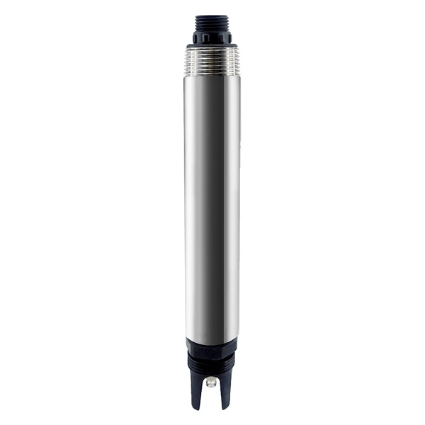
If you use ORP to follow denitrification, place the probe in a representative mixed zone—not beside recycle flow, carbon dosing or stagnant sludge. ORP sensor placement in anoxic tanks determines whether YexSensor YEX-S1PRO-ORP shows useful process trends or only a local hydraulic condition.
Why ORP Sensor Placement in Anoxic Tanks Matters
An ORP probe installed beside a recycle inlet may react to local oxygen carryover rather than the average tank condition. A probe in a dead zone may show an apparently stable reducing value while the main flow follows another path. Mounting directly beside carbon dosing can create short chemical responses that are not representative of biological performance. These errors cannot be repaired by calibration alone.
Before choosing a point, map influent, internal recycle, return streams, carbon addition, mixers, baffles, aeration leakage and outlet hydraulics. The selected point should see fully mixed water early enough to support the intended action. Large or staged tanks may need more than one point to distinguish inlet loading from endpoint conditions.
YEX-S1PRO-ORP Product Fit
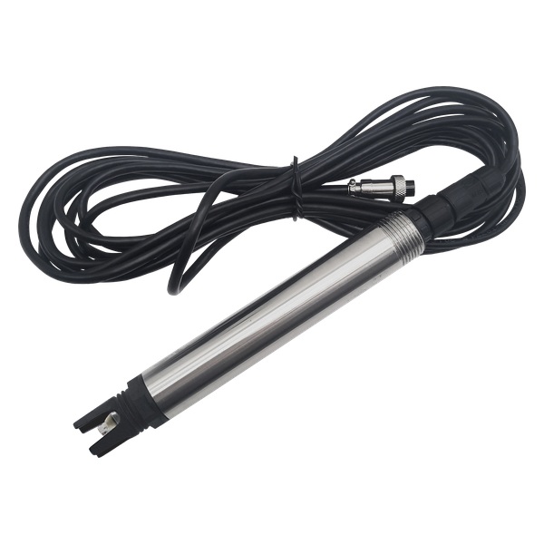
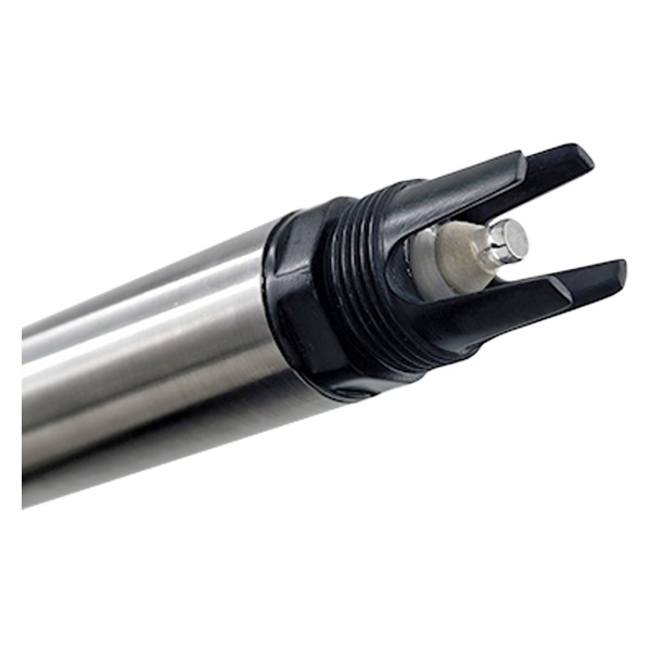
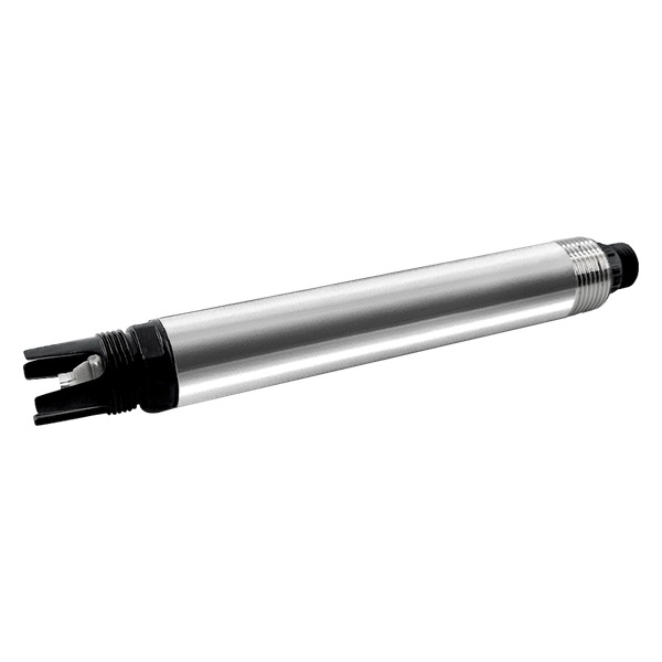
The official YEX-S1PRO-ORP information lists ORP and temperature, a −2000.0 to +2000.0 mV range, ±20 mV ORP accuracy, temperature accuracy of ±0.1°C and a 30-second response. The measurement principle is a high-performance ORP electrode with automatic temperature compensation.
Construction is 316L stainless steel plus ABS with IP68 protection. Power is 12–24 VDC at about 0.4 W. Output is RS485 Modbus RTU or optional 4–20 mA, selected at ordering. The probe uses a 5 m shielded cable by default and a 3/4 NPT immersion arrangement. The electrode head and connector must remain clean, with calibration performed when site verification indicates drift.
ORP Is a Process Indicator, Not a Nitrate Analyzer
ORP reflects the combined oxidizing and reducing environment created by dissolved oxygen, nitrate, nitrite, reduced compounds, carbon source, sulfide, pH and biological activity. A change can indicate a process transition, but the same millivolt value does not prove the same nitrate concentration in every plant. Build the operating interpretation from paired nitrate, DO and process data.
For control, look for sustained trends, slopes and repeatable transition behavior rather than importing a universal setpoint. Seasonal temperature, influent composition and carbon dosing can move the baseline. Keep a change-control record when thresholds are revised so operators can explain alarm history and avoid tuning the process around sensor drift.
Technical Parameters and Procurement Checks
| Selection item | Official specification or engineering meaning | Procurement check |
|---|---|---|
| Measured outputs | ORP and temperature | Define whether the value supports trend, alarm or dosing review |
| ORP range | −2000.0 to +2000.0 mV | Confirm expected anoxic and upset values remain inside range |
| Accuracy | ORP ±20 mV; temperature ±0.1°C | Set acceptance against a maintained reference electrode |
| Response | 30 seconds | Add mixing, transport and PLC persistence time |
| Principle | High-performance ORP electrode | Disclose sulfide, oils, coatings and poisoning risks |
| Output | RS485 Modbus RTU or optional 4–20 mA | Specify register, sign handling and analog bipolar scaling |
| Construction | 316L stainless steel plus ABS; IP68 | Review wastewater chemistry and cleaning agents |
| Power and cable | 12–24 VDC, about 0.4 W; 5 m shielded default | Confirm voltage drop, junction location and shielding |
| Installation | Immersion, 3/4 NPT | Approve depth, mixer clearance and retrievable holder |
| Maintenance | Keep electrode and connector clean; calibrate as required | Define verification trigger, cleaning method and spare probe |
Recommended and Unsuitable Locations
A useful point is normally downstream of initial mixing but before the anoxic-zone outlet, at a depth that remains submerged through operating levels. Protect the probe from mixer blades, carriers, rags and direct high-velocity impact. If internal recycle oxygen varies significantly, a second upstream point can help diagnose the source rather than forcing one probe to represent the whole basin.
Avoid stagnant corners, surface scum, floor deposits, aerated spray, chemical injection plumes and locations that technicians cannot safely retrieve. A bypass is possible only if sample transport, oxygen pickup and residence time do not destroy the redox condition being measured. Long exposed tubing can make an apparently convenient station unrepresentative.
Commissioning a Site-Specific ORP Interpretation
Collect ORP, DO, nitrate, flow, recycle, carbon dose and temperature together during stable operation and known disturbances. Identify repeatable relationships and define warning logic with the process team. Test whether the chosen point responds before the available intervention time expires.
Include plausibility rules for rapid jumps, dry exposure and communication loss. An invalid zero or frozen last value must not command dosing. When ORP participates in automatic control, use output limits, maximum dosing time, manual override and a documented fallback condition. Verify the full cause-and-effect sequence safely during commissioning.
Installation, Data Quality and System Integration
A sensor is only one part of the measurement point. The project also needs a representative location, rigid or retrievable mounting, cable protection, suitable power, a controller or gateway, documented communication settings and safe maintenance access. Install the measuring end in continuously renewed water and keep it away from direct chemical injection, trapped air, settled deposits and unrepresentative dead zones unless the approved design specifically requires that location.
For RS485 Modbus RTU, confirm power polarity, A/B convention, device address, baud rate, parity, stop bits and the register map supplied with the ordered revision. Use a unique address for every device on a shared bus, appropriate topology and termination, and separation from variable-frequency-drive or motor cables. If optional 4–20 mA is selected instead, define the engineering-unit scaling, fault behavior and PLC analog-input isolation before the purchase order is released.
Store the raw reading, unit, configured range, temperature, quality flag and maintenance state together. A number without context can appear valid after dry exposure, cleaning, a range change or communication recovery. Define warning, action, out-of-range, maintenance and communication-loss states separately. Use persistence or rate-of-change rules when bubbles, cleaning movements or hydraulic transitions can create short harmless spikes.
Commissioning should include mechanical inspection, stable-value confirmation, reference comparison, alarm simulation and communication-loss testing. Record the model, serial number, range, output, cable length, protocol revision and initial reference results.
Lifecycle Cost, FAT and Responsibility Boundaries
Evaluate ownership cost over the planned service period. Include mounting hardware, flow cells or bypass piping, junction boxes, controller inputs, gateways, standards, cleaning labor, consumables, replacement sensing parts, travel and downtime. A lower probe price can become the more expensive option if it requires unsafe weekly retrieval or if missing protocol documents delay PLC commissioning. Ask each supplier to separate included equipment from recommended accessories and customer-supplied items.
Write a factory acceptance checklist that verifies the ordered model, range, output, cable, connector, displayed units, Modbus communication and supplied documents. The site acceptance test should add installation inspection, comparison with the agreed reference method, alarm and interlock simulation, power-cycle recovery, communication-loss behavior and maintenance-state handling. Define who approves the sensor after cleaning or calibration and who may change ranges, addresses or setpoints.
Plan critical spares according to site access and consequence of failure. A remote station may need a complete exchange probe, while an accessible plant may hold cleaning tools, standards, seals or sensing elements.
How to Request a Comparable Quotation
Send the monitoring objective, process drawing, water source, minimum, normal and credible maximum values, temperature, pressure, pH, salinity or conductivity, suspended solids, oil or biological fouling risk, cleaning chemicals, mounting, cable length, power, PLC or gateway, output signal, quantity and destination.
Require line-item confirmation of the exact model, ordered range, measured and calculated outputs, housing and wetted materials, cable, connector, thread, mounting accessories, optional cleaning, controller, calibration materials, spares, drawings, protocol document, warranty, lead time and exclusions. Compare the installed and maintainable measurement point rather than the probe price alone. This makes quotations technically comparable and reduces change orders during commissioning.
Frequently Asked Questions About ORP sensor placement in anoxic tanks
Where should an ORP sensor be placed in an anoxic tank?
Use a fully mixed representative zone downstream of major inlet mixing and away from dosing plumes, aeration carryover, stagnant corners and deposits. Keep it safely retrievable and continuously submerged. Mark the proposed elevation and distance from recycle, carbon dosing, mixers and outlet on the drawing, then require supplier review before bracket fabrication. Verify the proposed point during different recycle and mixer conditions before final bracket approval.
Can ORP directly measure nitrate?
No. ORP reflects the combined redox environment. Correlate it with nitrate, DO, flow and dosing data before using it as a denitrification indicator. If nitrate removal is the contractual objective, specify the nitrate reference method and paired testing plan instead of accepting ORP alone as proof. Keep paired nitrate and DO results with the ORP trend so operators understand its site-specific meaning.
Does every anoxic tank use the same ORP setpoint?
No. Water composition, pH, temperature, carbon source and process design shift the response. Develop warning and action levels from plant data. Require site-derived warning and action logic in the control narrative, including persistence, reset, maximum dosing time and manual override. Review setpoints after major influent, carbon-source or process changes rather than copying historic values.
How many ORP sensors are needed?
One may be sufficient for a small well-mixed tank. Staged or hydraulically complex basins may need upstream and downstream points to separate loading from endpoint behavior. Ask bidders to price each point, mounting assembly, cable route and spare probe separately after the hydraulic zones have been defined. Provide separate alarm and maintenance responsibilities for every point included in the purchase.
Can YEX-S1PRO-ORP connect to a PLC?
Yes. Select RS485 Modbus RTU or optional 4–20 mA. Confirm signed values, register format, scaling, quality states and communication-loss behavior. The order must identify RS485 or 4–20 mA, signed mV handling, address, register format, scaling and safe behavior after signal loss. Test negative values, decimal position and loss-of-signal logic before enabling automatic dosing decisions.
How often should the probe be calibrated?
Use verification results and site drift to set the interval. Clean first, compare with a maintained reference and avoid unnecessary calibration that hides a location or fouling problem. Require the quotation to include the reference electrode, cleaning materials, verification tolerance, record form and replacement trigger in the spare-parts package. The operating procedure should state who can calibrate the probe and who approves its return to service.
What causes unstable ORP readings?
Common causes include poor mixing, bubbles, coating, sulfide, chemical slugs, loose mounting, dry exposure, electrical noise and a changing process—not only electrode failure. Provide these process conditions in the RFQ and require YexSensor to review whether protection, relocation, different sampling or maintenance is appropriate. Require troubleshooting guidance that starts with hydraulics and fouling before recommending recalibration or replacement.
Can a bypass be used?
Only if transport and oxygen pickup do not change the redox condition. Keep tubing short, flow controlled and the sample point representative, with isolation and drain. Require confirmation of tubing length, flow, residence time, oxygen exclusion, isolation and drain before approving a bypass installation. Compare bypass and direct-immersion response under real process conditions before accepting the arrangement.
What RFQ information is required?
Provide tank drawing, flows, recycle, dosing and aeration points, expected ORP, pH, temperature, chemistry, mounting, cable, output, PLC, reference checks and quantity. When requesting a quotation, this allows coverage of YEX-S1PRO-ORP, a retrievable holder, cable, controller documents, reference tools and commissioning responsibilities. Ask bidders to identify supplied brackets, junctions, references, spares and on-site services as separate lines.
Final Thoughts
For representative anoxic-zone monitoring, review the YEX-S1PRO-ORP with YexSensor. Send your tank layout, recycle and dosing points, expected ORP, installation, PLC and validation plan to receive a project-specific quotation.



