


 Chinese
 Spanish
 French
 Russian
 German
 Portuguese
 Indonesian
 Thai
 Vietnamese
 Arabic


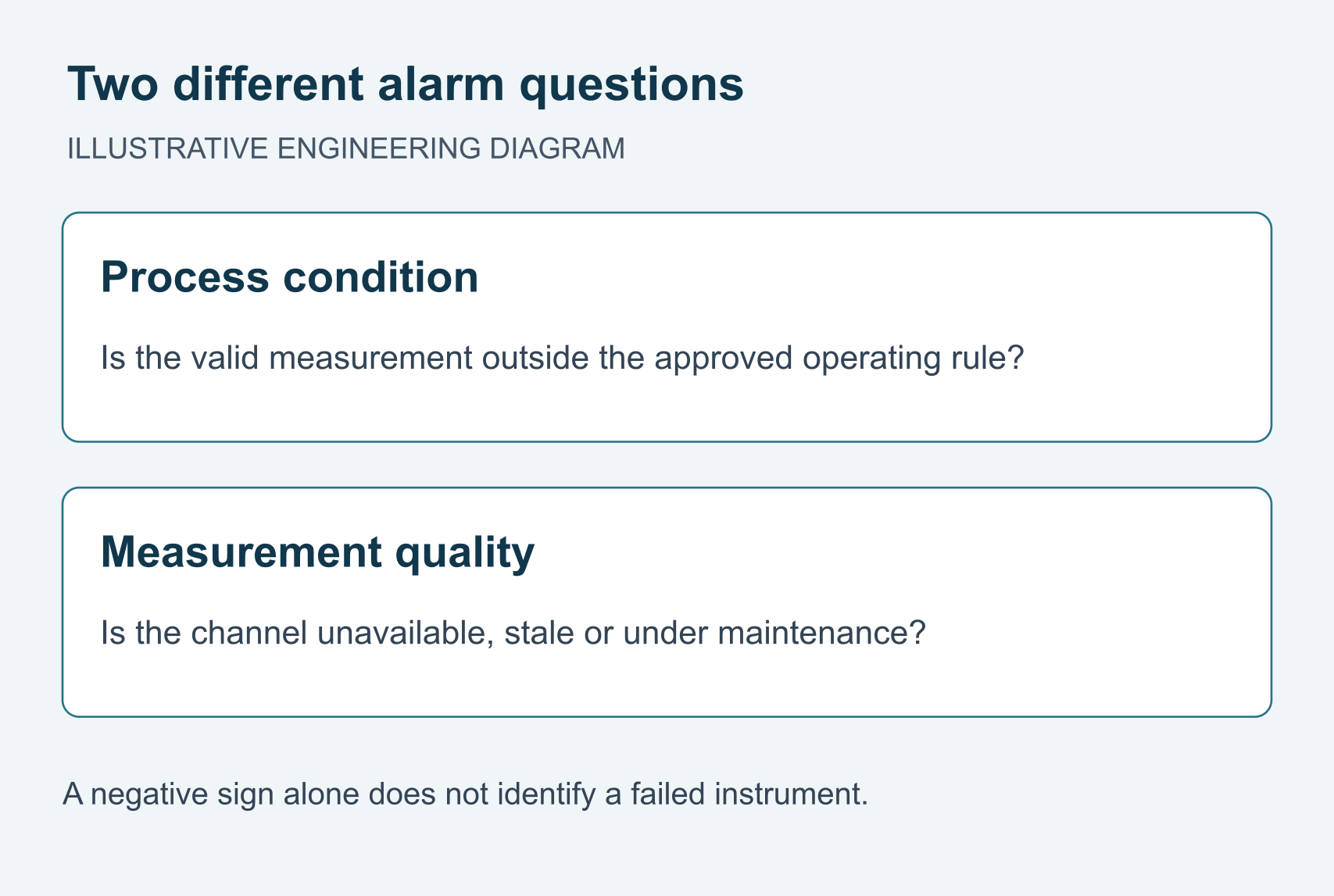
Negative ORP readings are not automatically sensor faults. They can represent reducing conditions, but reference differences, electrode condition and incorrect data decoding can also explain an unexpected value. Integrators should verify the measurement chain before replacing a probe or changing wastewater process controls.

What negative ORP readings actually tell you
ORP is a measured potential between a sensing electrode and a reference electrode in the sample. Its sign belongs to that measurement arrangement. A negative value is not a negative concentration, and zero is not a universal boundary between acceptable and unacceptable wastewater.
Review sampling location, process stage, pH, temperature and recent chemical additions alongside the signal. Do not infer a specific chemical concentration from ORP alone.
This distinction matters when a supplier is asked to replace a supposedly faulty sensor. Replacing a functioning probe will not correct a wrong register interpretation, an unrepresentative mounting point or an inappropriate process threshold.
Locate the fault before replacing the probe
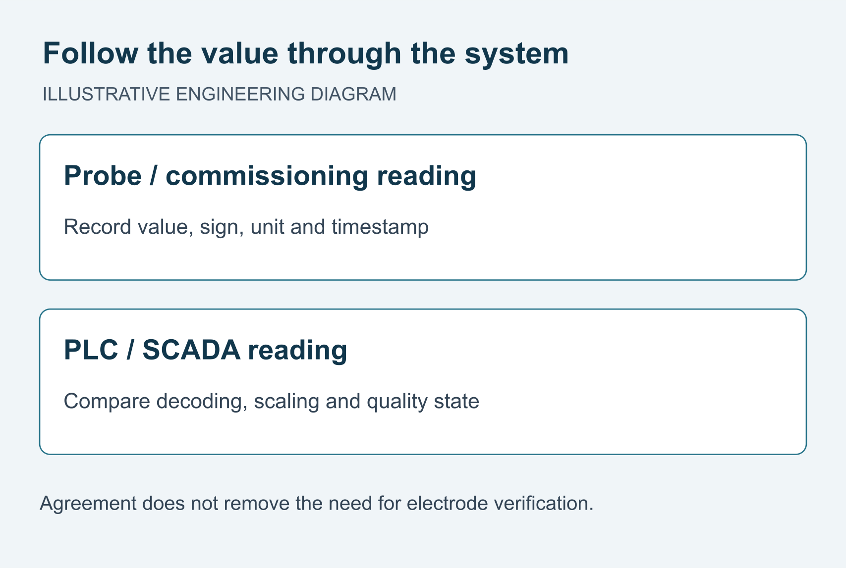
Record the timestamp, process state, device identity and original settings before making changes. Compare readings obtained under the same conditions.
| Observation | Investigate first | Useful evidence |
|---|---|---|
| Probe reading is plausible; PLC differs | Data representation, scaling and units | Raw response and decoded tag at the same time. |
| Every display agrees on a negative value | Process location, reference and electrode condition | Verification result plus dosing and mixing history. |
| Signal changes only after a valve or dosing event | Sample delay and local chemical exposure | Time-aligned valve status and measurement trend. |
| Value freezes after disconnection | Stale-value and quality handling | Last update time and communication-fault record. |
Change one item at a time. Replacing the probe will not resolve a host decoding error.
Compare the documented configurations, not the series labels
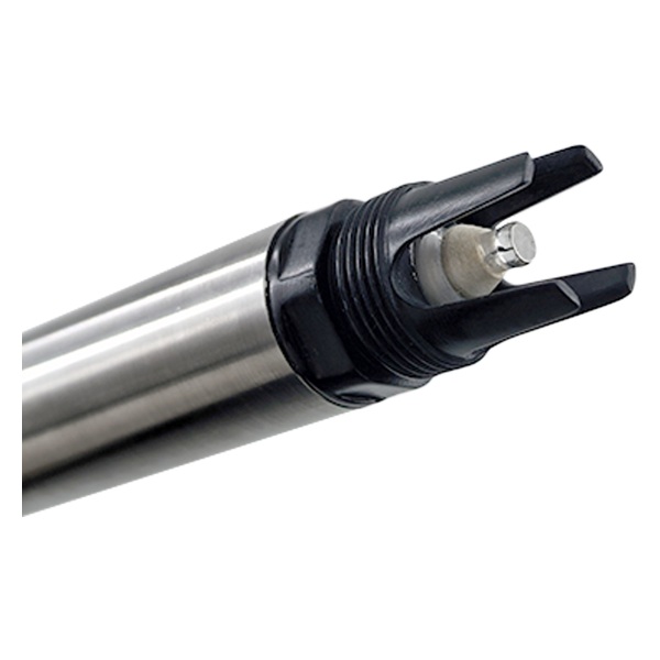
Review YEX-S2-ORP-S for a retrofit needing its documented interface configuration and service procedure. The existing manual describes one-point calibration. This is a reason to review its maintenance workflow, not proof that it performs better in every wastewater stream.
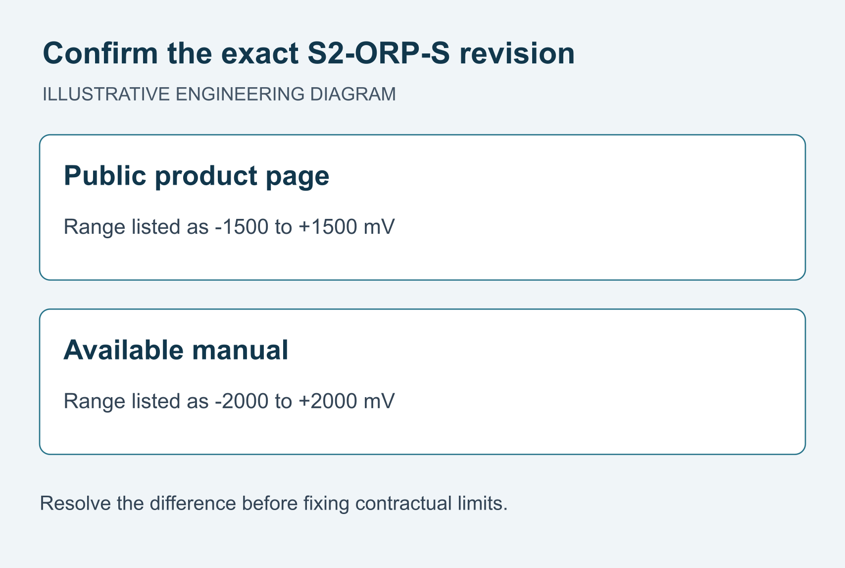
Resolve a documentation conflict before ordering: the public page lists −1500 to +1500 mV, while the available manual lists −2000 to +2000 mV. Obtain a matching, current specification for the delivered version. Do not combine the wider range with unrelated specifications to create a fictional configuration.
S1PRO-ORP remains a separate option for a compatible non-seawater duty. Neither that stainless-steel model nor S2-ORP-S should be offered as a seawater solution on the strength of housing material alone. Selection follows exposure, service access and verified interface requirements.
| Parameter | Documented specification | Procurement check |
|---|---|---|
| Range | Page: ±1500 mV; available manual: ±2000 mV | Resolve the version conflict before contractual acceptance. |
| Resolution and accuracy | Manual: 1 mV; ±6 mV | Require confirmation against the delivered revision. |
| Supply and consumption | Manual: 12–24 V DC ±10%; 0.2 W at 12 V | Check the complete channel power requirement. |
| Output | RS485 Modbus RTU; optional 4–20 mA | Confirm the supplied configuration and concurrent-output behavior. |
| Wetted material | Manual: 316L stainless steel | Not a seawater recommendation; check actual chemistry. |
| Operating limits | Manual: 0–65°C; <0.1 MPa | Confirm the order revision; do not use S1PRO limits. |
| Mounting and cable | Immersion; NPT 3/4; 5 m cable | Confirm cable jacket and electrode orientation. |
| Calibration and protection | One point; IP68 | Obtain current service and verification instructions. |
Review S1-ORP for an RS485-only channel.
Compare the documented S1PRO configuration.
Table evidence: YEX-S2-ORP-S product page and supplied YEX-S2-ORP-S User Manual (revision/date not established). Manual-derived rows are labelled. The conflicting ranges are not selectable options; obtain a current matched specification.
Check signed data, scaling and the host display
Use the exact register documentation for the supplied firmware. Determine whether the measurement is a signed integer, floating-point value or another defined representation. Confirm byte or word order where applicable, scaling and units. A generic Modbus connection does not guarantee correct interpretation of the payload.
An unsigned interpretation of signed negative data can produce a large positive value. This is a diagnostic pattern, not proof of the encoding used by this particular sensor. Do not guess a register type or write undocumented values to the device.
For an analog version, compare the confirmed current-to-millivolt mapping with the PLC scaling. Check the configured endpoints and fault handling. Reversing RS485 wires is not a correction for negative chemistry readings; communication wiring and measurement sign are separate issues.
The available S2-ORP-S manual includes a model-specific negative-value decoding example. Confirm that convention against the supplied firmware; do not assume a generic signed-integer routine reproduces every legacy device.
Separate electrode condition from reference differences
A coated or poorly conditioned sensing surface may respond slowly or behave inconsistently. Inspect and service it according to the model’s instructions, then verify with the approved checking procedure. Avoid an improvised abrasive cleaning method that could change or damage the sensing surface.
Two ORP instruments may use different reference arrangements or reporting conventions. Their displayed numbers are not automatically comparable, even in apparently similar water. Record the reference information and avoid applying an offset borrowed from an unrelated electrode.
Temperature and pH help interpret the process, but a universal temperature correction cannot transform every wastewater ORP measurement into an equivalent value. Clarify what any compensation feature actually does. Use the same sample conditions for comparisons and document the procedure rather than forcing agreement through an unexplained adjustment.
Apply the diagnosis to three engineering situations
These examples describe diagnostic approaches, not measured customer results. In an anoxic treatment zone, a negative signal may be consistent with the operating environment. The integrator should correlate it with process status and other relevant measurements. The benefit is avoiding a false sensor-failure alarm based only on sign.
In a chemical treatment tank, an unexpected change after dosing requires review of mixing, sensor location and the approved process sequence. An electrode beside the injection point may see a local condition that does not represent the bulk liquid.
During a control-panel retrofit, a negative reading shown correctly by one host but incorrectly by the new PLC points toward configuration review. Comparing the same device across the two paths helps the panel builder isolate integration work from a needless probe replacement.
When S1 is sufficient and when another configuration is needed
Treat series selection as a fit check, not a ranking. S1-ORP documents −1500 to +1500 mV, POM wetted material and one-point calibration.
| Project requirement | Candidate | Decision boundary |
|---|---|---|
| RS485-only channel | S1-ORP | Choose when range, exposure and servicing meet the duty. |
| Analog input required | Documented S2-ORP-S output option | Confirm delivered output behavior and resolve the range discrepancy. |
| Different mechanical or wetted requirements | Separately reviewed S1PRO-ORP configuration | Compare actual limits, not the PRO label. |
| Seawater or saline exposure | Application-specific confirmed configuration | Do not recommend stainless-steel S1PRO; plastic alone is not approval. |
If S1 meets the duty, verify it before replacement. Require a specific reason for any model change.
Specify a fault-handling and handover test
Commission the measurement and its quality state together. Check the engineering value, sign, range and units at the host. Safely test communication loss and maintenance states, and confirm that a stale value is identified rather than silently treated as current process data.
Do not use an unverified negative-value threshold as an automatic fault flag. The process designer defines operating alarms, while the instrumentation team defines channel-quality alarms. These may require different responses and different permissions to reset.
Hand over the register map revision, configuration record, comparison method and service procedure with the instrument. For background on reference systems, consult the Hach ORP technical guidance; its procedures and numerical offsets must not be assumed to apply to a different manufacturer’s electrode.
Technical references
Review the measurement package
Share water chemistry, range, interface and fault records. Ask whether S1 meets the duty or a specific S2/S1PRO configuration resolves an unmet requirement. Include quantity and installation details.
S1-ORP: RS485 candidate · S2-ORP-S: confirm output and revision · S1PRO-ORP: separate non-seawater configuration. Send Your Project Requirements.
Frequently Asked Questions
Q1. Are negative ORP readings normal in wastewater?
They can be credible in reducing conditions, but the sign alone does not establish correct operation or sensor health. Interpret the value with the reference system, process stage and verification results. Before ordering a replacement, ask the integrator to compare the same measurement through the sensor, PLC and display and investigate where any disagreement begins.
Q2. Why does my PLC show a large positive number instead of a negative value?
One possible cause is interpreting signed data as unsigned, although other decoding or scaling errors can produce incorrect values. Confirm the actual register type and byte or word order from the delivered device documentation. Do not guess from the symptom alone. Require a commissioning record showing agreement between the source measurement and the host engineering value.
Q3. Can temperature compensation make two ORP sensors agree?
Not necessarily. ORP depends on the reference arrangement and the sample’s chemistry, and there is no universal correction that makes all wastewater measurements equivalent. Record temperature, pH and reference details during comparison. Ask each supplier what its compensation feature means before accepting a numerical offset or treating agreement after adjustment as proof of accuracy.
Q4. When should I retain S1 instead of specifying another series?
Retain S1 when its documented range, RS485 interface, wetted compatibility and service procedure already meet the duty. First correct sampling or decoding faults and verify the channel. Request a different configuration only for an identified unmet requirement, such as an independently confirmed analog interface need; a negative value alone does not justify replacement.
Q5. When is S1-ORP sufficient for the project?
S1-ORP is worth selecting when its documented −1500 to +1500 mV range, RS485 Modbus RTU interface and POM wetted construction meet the actual duty. Verify chemistry, installation and maintenance requirements before ordering. Compare another configuration when a specific requirement is unmet; negative readings alone do not justify changing to S1PRO or S2.
Q6. Should I choose RS485 Modbus RTU or 4–20 mA?
Use the interface required by the panel and verify its delivered configuration. RS485 requires the correct map and decoding; 4–20 mA requires confirmed endpoints and host scaling. The S2-ORP-S documentation lists an optional analog output. Obtain confirmation before designing simultaneous analog and digital acquisition rather than assuming that capability from the series name alone.
Q7. What should an ORP replacement quotation include?
Ask for the exact order code, confirmed range, output configuration, wetted materials, current manual and commissioning support. Include the fault record and verification results so the supplier can assess whether replacement is needed. Require written resolution of conflicting specifications before acceptance, together with delivery, spare-part and warranty terms for the proposed configuration.
Q8. What should the project acceptance test include?
Include correct value, sign, units and host interpretation under agreed checking conditions, plus communication-loss and maintenance handling. Record the reference arrangement and checking method so comparisons are reproducible. Ask for configuration files and document revisions at handover. A successful serial connection alone does not demonstrate that the process value is correctly interpreted or usable.
Q9. Can ORP replace a specific chemical concentration measurement?
Not generally. ORP reflects a combined electrochemical condition rather than directly identifying the concentration of every oxidant or reductant in mixed wastewater. If dosing or acceptance depends on a specific concentration, define the appropriate analytical method separately. Position the ORP channel as supporting process evidence unless the proposed relationship has been validated for the actual duty.
Summary
Negative ORP readings require diagnosis before replacement. Compare the signal path, electrode condition, reference and process location. Consider S1-ORP when its range, RS485 interface and wetted compatibility meet the duty. Review S2 for a documented interface need, resolving its range discrepancy before ordering. Demonstrate correct negative-value interpretation and separate process alarms from channel faults. Provide fault records, verification results and installation conditions so the selected configuration solves an identified requirement.


