


 Chinese
 Spanish
 French
 Russian
 German
 Portuguese
 Indonesian
 Thai
Thai Vietnamese
 Arabic

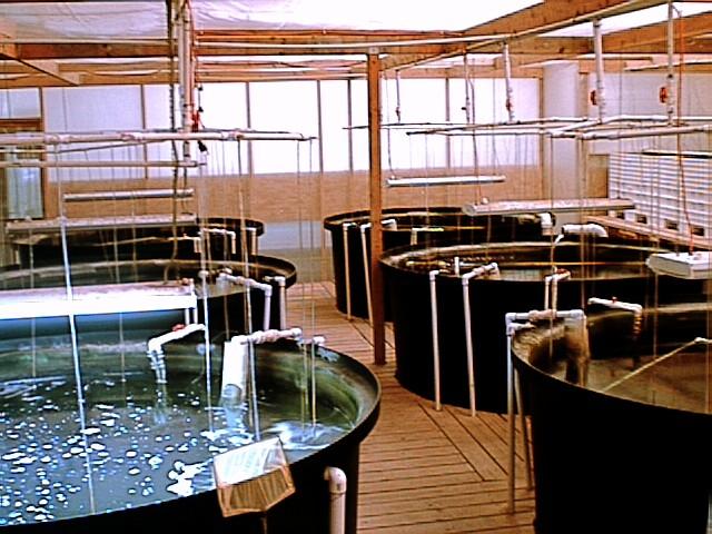
What an Indoor Aquaculture Monitoring System Includes
Indoor aquaculture tank monitoring combines water quality sensors, a local controller or data logger, and an alarm workflow for the tanks being managed. In a recirculating aquaculture system (RAS), the monitoring package should identify both the physical tank and the water condition behind each reading. The purpose is to help operators investigate oxygen decline, changes in water chemistry and nitrogen loading before deciding on a response.
For a nursery room or indoor fish farm, define the tank groups, water circuits and operator response first. A compact sensor package can provide useful local monitoring; a remote dashboard adds another layer of communication and service responsibility. The configuration depends on species, life stage, stocking conditions and the existing oxygen-supply and water-treatment equipment.
Choose Parameters for the Operating Decision
| Parameter | What the trend helps investigate | What to define in the specification |
|---|---|---|
| Dissolved oxygen (DO) | Oxygen availability at the measured tank location. | Species-specific operating targets, measurement range, alarm response and a representative installation point. |
| pH and water temperature | Changes in water chemistry and the conditions needed to interpret other readings. | Required channels, reference checks and the compensation used by the selected instruments. |
| Ammonium / nitrogen channel | Nitrogen loading and changes that may warrant a biofilter or feeding review. | Whether the output is NH4+, NH4-N, total ammonia nitrogen or a compensated NH3 result, with the exact unit. |
| Conductivity / salinity | Source-water or salt changes where these are relevant to the culture system. | The expected range and whether conductivity or a configured salinity result is required. |
Ammonium (NH4+) and un-ionized ammonia (NH3) are different forms. Their balance depends on pH and temperature, so an ammonium reading must not be treated as a direct NH3 reading. A controller label alone does not establish the measured form. The supplied model documentation and agreed reference checks should define how the nitrogen result is interpreted. See the USGS explanation of ammonia and ammonium.
Local Monitoring and Remote Communication
Typical signal path: tank sensors → the ordered RS485 Modbus RTU or analog interface → compatible controller, PLC or data logger → optional gateway/network → SCADA or remote platform.
The sensor output and the remote communication link are separate parts of the system. RS485 does not itself provide 4G or a cloud connection. For a local installation, confirm the display, trend storage and alarm outputs supplied by the controller. For remote monitoring, also confirm the gateway, network coverage, platform compatibility and what remains available when the network fails.
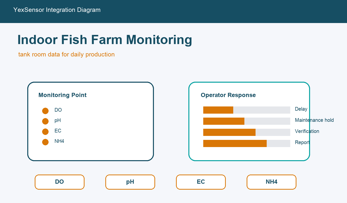
The overview illustrates monitoring channels and operator-response considerations. The final wiring and network drawing should identify each tank, sensor, controller, power supply and communication link.
| System layer | Include in the package | Check before handover |
|---|---|---|
| Tank measurement | Selected sensors, holders, cable protection and access for cleaning. | The point represents the intended water circuit and can be serviced safely. |
| Local controller / PLC | Compatible inputs, engineering units, named tank channels and agreed alarm functions. | Displayed values match the sensor output and invalid readings are identified. |
| Optional remote access | Gateway, network connection and agreed data destination. | Communication-loss behavior, data recovery and remote access work as specified. |
YexSensor Sensor Options for Indoor Fish Tanks
The following models are options for the measurement layer. Select the channels that support the farm’s operating decisions, then confirm each model’s current datasheet and ordered configuration. The package scope should separately identify the controller, gateway, mounting accessories and service materials.
| Sensor to review | Role in the tank monitoring system | Configuration to confirm |
|---|---|---|
YEX-S1-RDO Optical Dissolved Oxygen Sensor | Dissolved oxygen trends for oxygen-supply checks and tank alarms. | Confirm the supplied output, expected oxygen range, cleaning access and replacement-cap requirements. |
YEX-S1-PH Industrial Online pH Sensor | pH trends for interpreting water chemistry and investigating changes after water exchange. | Confirm calibration materials, storage instructions and controller compatibility. |
YEX-S1-EC Online Conductivity Sensor | Conductivity trends where source-water or salinity changes matter to the production system. | Specify the expected conductivity range; confirm whether a salinity result is supplied and how it is configured. |
YEX-S1-NHN Online Ammonium Nitrogen Sensor | An ammonium-related trend where nitrogen loading and biofilter checks are part of the monitoring plan. | Confirm the reported chemical form, unit, compensation requirements and reference-check procedure. |
Plan Tank Groups Before Adding More Probes
Start with a tank list and water-circuit drawing. Tanks sharing a treatment loop may still differ in feeding load, stocking conditions or local oxygen supply. A reading from the common return describes that measurement point; it does not prove that every tank has the same conditions.
Use initial checks at candidate locations to decide which points need continuous monitoring. Give each channel a physical tank or circuit name, and match those names on the probe label, controller and alarm message. Detailed placement guidance is available in the tank aquaculture sensor placement guide.
Make Alarms and Commissioning Testable
Set operating targets with the farm team for its species and production stage. For each alarm, define the limit, delay, reset condition, responsible person and first inspection step. Keep low oxygen, sensor fault and communication loss as distinct states. Maintenance periods should be identifiable rather than appearing as valid process readings.
During commissioning, check the complete signal path and record the unit, scaling, sensor address and applicable register map. Test an alarm safely without deliberately creating harmful water conditions. Also check controller behavior after a power interruption and gateway behavior during a network interruption. Record the settings and test results before accepting remote notifications or automatic equipment control.
Information Needed for a Sensor Package Quotation
Send the tank count and dimensions, species and production stage, water-circuit arrangement, expected water conditions and required parameters. Include the existing controller or PLC, preferred output, cable distances, power supply, local or remote monitoring requirement, quantity and delivery country.
A quotation should show which sensors, holders, cables, controller functions, gateway services and calibration materials are included. For a pilot, define the acceptance checks and maintenance responsibility before extending the same configuration to more tanks.
Frequently Asked Questions
Which parameters should an indoor fish tank monitoring system include?
Start with the operating risks and required responses. DO, pH and temperature are common channels to assess; add a nitrogen or conductivity channel when it helps a defined feeding, biofilter or water-source decision. Confirm the chemical form and unit of any nitrogen result.
Can one set of sensors monitor several tanks?
A common-loop measurement provides information about that location. It may miss conditions in individual tanks. Determine the point count from the water circuits, tank loading, site comparisons and the consequences of a missed alarm.
Does an RS485 sensor connect directly to a cloud platform?
RS485 supplies a local electrical communication interface. Remote transmission needs a compatible controller, data logger or gateway with the required network and platform connection.
What should remain available if the remote network fails?
Specify the required local display, recording and alarm behavior with the controller supplier. Test that behavior during commissioning; do not assume that a remote platform provides a working local fallback.
Can the system switch aerators automatically?
Automatic switching requires a compatible controller or PLC, suitable outputs and a validated control plan. Confirm equipment interlocks, fault handling, maintenance behavior and manual operation before enabling control. Sensor readings alone do not define those functions.
Is an ammonium reading the same as an ammonia toxicity reading?
No. Verify whether the channel reports NH4+, NH4-N, total ammonia nitrogen or a compensated NH3 value. The ammonia–ammonium balance depends on pH and temperature, and the output must be interpreted using its documented chemical form and unit.
What proves that the monitoring package is ready to use?
The tank labels and channels match, readings use the correct units and scaling, alarm and fault tests pass, and the operators can remove and maintain the probes safely. Keep the wiring, communication settings and commissioning records with the system.
What is a practical first step for a new indoor farm?
Define one pilot tank or circuit and the decisions its readings will support. Validate installation, alarms, reference checks and cleaning workload before repeating the configuration across the farm.
Related Aquaculture Monitoring Guides
Sensor priorities for intensive fish farming — parameter selection under high feeding and production loads.
Tank sensor placement and blind spots — choosing physical measurement locations.
Smart aquaculture water quality monitoring solution — broader system options.
Water quality sensor selection FAQ — configuration questions before ordering.



