


 Chinese
 Spanish
 French
 Russian
 German
 Portuguese
 Indonesian
 Thai
 Vietnamese
 Arabic


Start with the decision the alarm must support
Drip irrigation turbidity monitoring can flag changes in suspended-particle conditions, but it cannot establish a universal filter backwash threshold. Select the measuring point according to the action required: upstream monitoring identifies changes in source water; downstream monitoring checks the water delivered beyond the filter. Use differential pressure and flow to assess filter operation, then validate the alarm against actual samples and emitter performance.
For an irrigation OEM, the practical purchase is a monitoring package with an agreed response procedure. Buying a sensitive probe without defining whether the controller should warn, backwash or stop irrigation leaves the most important engineering decision unresolved.
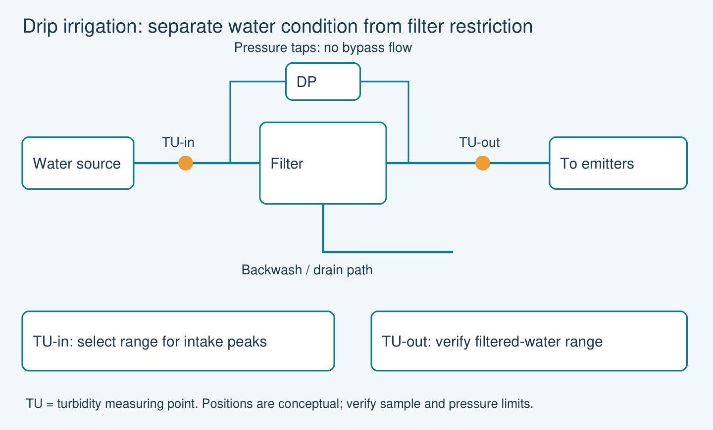
The buyer risk: clear water can still cause blockage
A stable turbidity reading does not rule out mineral precipitation or biological growth. These mechanisms need water analysis and a treatment assessment. FAO’s irrigation-water guidance separates physical particles, chemical deposits and biological growth as contributors to emitter clogging. A turbidity channel therefore complements the irrigation maintenance programme; it does not replace chemical testing.
Before requesting a quotation, list the failure you are trying to detect. Sediment entering after a storm, a damaged filter element and gradually accumulating deposits are different problems. An alarm tuned for one may be insensitive to another. Do not translate an NTU value directly into particle size, emitter blockage probability or suspended-solids concentration without site-specific evidence.
Match the sensor range to filtered-water conditions
The official YEX-S2-ZSA listing identifies a low-turbidity instrument with a displayed range of 0–10.000 NTU and RS485 Modbus RTU output. These published facts illustrate a low-range measurement channel, but they do not establish irrigation suitability. This guide does not recommend ZSA for the project: the product page and its linked manual disagree on accuracy and working temperature, and the page gives inconsistent enclosure ratings. A common range and interface are insufficient to approve the complete installation.
If upstream storm peaks exceed the specified span, select a suitable higher-range instrument for that point. Do not borrow the range of another YexSensor turbidity model. Use the official linked manual together with a configuration-specific installation drawing. Resolve the conflicting specifications before choosing this model; do not approve a sample cell, pressure arrangement, outdoor enclosure or cleaning method from the range alone.
Product reference: YEX-S2-ZSA specifications and integration information.
Specification boundaries for the quotation
| Check | Evidence boundary | Purchase implication |
|---|---|---|
| Published range | 0–10.000 NTU | Check actual filtered-water peaks before specifying this low-range channel; use a separately qualified instrument if peaks exceed the span. |
| Communication | RS485 Modbus RTU | Confirm the ordered register map and fault indications with the controller supplier. |
| Installation qualification | Published accuracy, temperature and enclosure information is inconsistent | Exclude ZSA from a firm recommendation until the supplier provides consistent configuration-specific documents; assess a documented alternative against the same site requirements. |

Compare measurement layouts before buying
A downstream-only channel is often easier to maintain and directly observes delivered water, but it cannot distinguish a changing inlet from a deteriorating filter without other information. Paired upstream and downstream monitoring provides more context, although the two sensors may require different ranges.
Select the arrangement that observes the failure requiring action, then verify its coverage during commissioning.
| Arrangement | Question answered | Purchase decision |
|---|---|---|
| Downstream only | Delivered-water change | Select a documented range covering actual filtered-water peaks and verify sample conditions; retain differential-pressure monitoring. |
| Upstream and downstream | Source change versus filtration performance | Specify each range separately and align timestamps and sample delays. |
| Differential pressure plus flow | Hydraulic loading and restriction | Retain these measurements; a turbidity reading cannot replace them. |
| Sampling and water analysis | Deposits despite low turbidity | Investigate chemical and biological causes before buying more optical channels. |
Three field scenarios that require different responses
After rainfall, upstream water may change rapidly while filtered water remains stable. Record both conditions and filter differential pressure before changing the cleaning sequence. An upstream spike alone does not prove that poor water reached the emitters.
After filter service, a sustained downstream increase warrants a check of seals, assembly and bypass positions. Take a representative sample and inspect the optical window before concluding that the filter failed.
During a dry season, emitters may lose output while turbidity remains low. Check distribution pressure, deposits and relevant chemistry. Purchasing another turbidity sensor will not diagnose a scale-forming mechanism by itself.
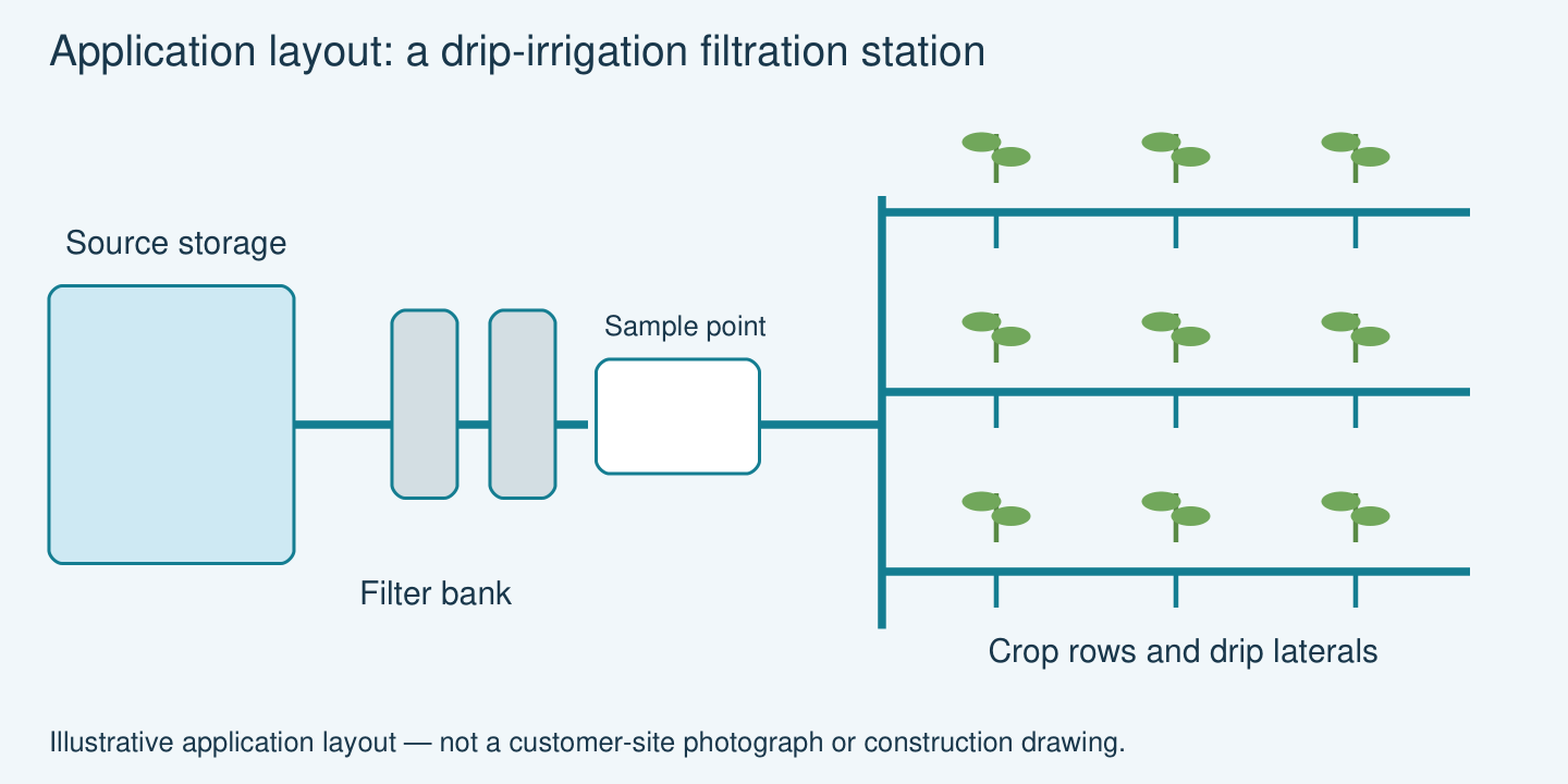
Installation, controller logic and commissioning
Locate a sample takeoff in moving, representative water. Avoid stagnant pockets and arrangements that settle out particles before measurement. A bypass must protect the sensor within its confirmed operating envelope while preserving a representative sample. Include isolation, safe drainage and access for cleaning.
Air entrained after pumping or backwash can disturb an optical reading. Investigate bubble behaviour during commissioning instead of masking every spike with a long averaging interval. A long delay may also hide a genuine breakthrough event.
Log turbidity, differential pressure, flow, pump state and backwash state on a common clock. Flag stale data, communications loss and out-of-range readings separately from a water-quality alarm. Agree how alarms behave during an intentional backwash and how normal monitoring resumes.
Build the initial alarm from observed acceptable operation and confirmed adverse samples. Test it across source-water changes and maintenance cycles. The commissioning record should show the measured event, the operator action and whether that action resolved the problem.
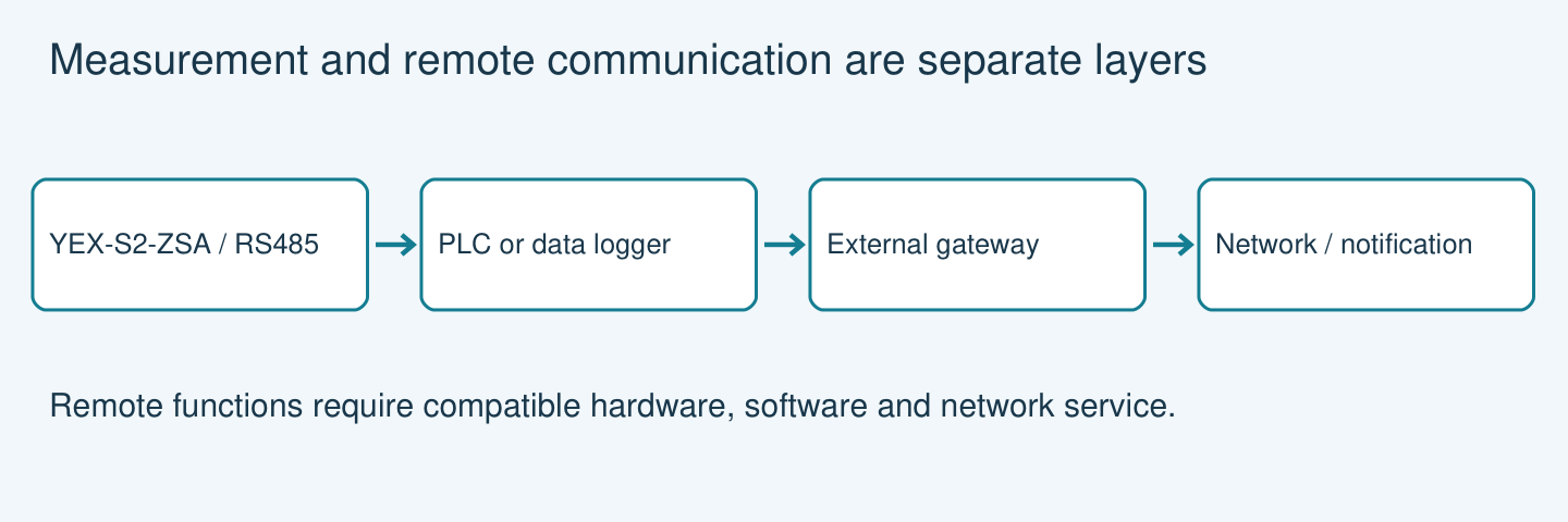
The diagram shows the published RS485 interface of YEX-S2-ZSA as a communication example, not an approved irrigation installation. A compatible PLC or data logger reads the signal and implements the approved monitoring logic. Remote notifications require a separately specified gateway, network service and software; they are not inherent features of the probe.
For a station that also needs chemical-condition measurements, compare the water quality sensor range by measured parameter. Turbidity, pH and conductivity answer different questions; none is a substitute for the others.
Make the alarm acceptance test repeatable
- Define normal operation. Record filtered-water readings with sample results, pressure difference, flow and the filter operating state. Keep startup and backwash transitions identifiable.
- Define the event requiring action. Agree whether a confirmed change prompts inspection, a filter check or a controlled stop. Do not create a damaging event in the crop system merely to test an alarm.
- Test the decision path. Use an approved controlled test or recorded event to check persistence, reset behaviour, operator acknowledgement and missing-data handling. A simulated PLC signal tests logic, not optical measurement performance.
- Agree acceptance evidence. Retain the paired sample and trend, alarm timestamp, response and recovery record. If measurement noise or normal variation overlaps the intended trigger, revise the design before enabling automatic action.
RFQ checklist for a complete filtration monitoring package
Provide the water source; normal and storm-event samples; filter technology and rating; inlet and outlet pressure; pipe arrangement; available sample flow; minimum, normal and peak turbidity; controller interface; cable route; and number of stations. Include the action expected from each alarm.
Ask the quotation to separate the sensor, sample assembly, controller or gateway, cleaning accessories and commissioning support. Request the exact range, manual revision, installation drawing, register map and acceptance procedure. State who will establish the final alarm limits and who will maintain the sample path.
Technical references
- YexSensor model specifications
- YEX-S2-ZSA linked manual: compare configuration and installation limits
- FAO: water quality and clogging of localized irrigation systems, Section 5.7
Discuss Your Project Requirements
Send the project data listed in the RFQ checklist above, together with your quantity, destination, installation drawing and acceptance requirements. Identify any mandatory documentation and the decision the measurement must support.
Use the YEX-S2-ZSA product specifications as a comparison reference, not as a confirmed selection. Request a consistently documented model that meets the submitted water and installation conditions.
- Water source and normal/peak turbidity at each proposed point
- Filter type, pressure difference, flow and sample-return or drainage arrangement
- Required alarm action, PLC interface, quantity and delivery destination
FAQ
Q1. What NTU value should trigger a filter alarm?
There is no universal value for this application. Establish a baseline using the actual water, filtration arrangement and acceptable emitter operation. Validate an initial alarm with samples and documented events before allowing it to initiate automatic action. Include this commissioning work in the project scope.
Q2. Does turbidity measure particle size?
No. It is an optical response to the sample, not a particle-size distribution. If the purchase decision depends on a filter rating or emitter passage size, request appropriate particle information and filtration guidance alongside turbidity measurements.
Q3. Can bubbles create a false alarm?
They can disturb optical measurements. Check pump transitions, backwash and sample-cell air release before extending the alarm delay. The specified mounting and sample arrangement should keep representative water at the measurement surface without trapping air.
Q4. Should the probe be installed before or after the filter?
Choose downstream when the main question is delivered-water quality. Add upstream information when source-water changes must be distinguished from filter behaviour. Specify the range separately for each location rather than ordering two identical sensors automatically.
Q5. Is YEX-S2-ZSA appropriate for muddy intake water?
Do not assume so. Its official listing presents a low-turbidity span of 0–10.000 NTU. Compare actual intake peaks with the confirmed configuration; if they exceed it, request another range or model and its own supporting documentation.
Q6. Can one sensor replace differential-pressure measurement?
No. The measurements answer different questions: optical water condition versus hydraulic restriction. For a backwash project, retain the filter manufacturer’s hydraulic criteria and use turbidity as additional evidence for water-quality changes.
Q7. What samples should an integrator provide?
Supply normal filtered water and representative adverse samples, with collection points and operating conditions identified. Include storm or cleaning transitions where relevant. These samples help evaluate range suitability and the usefulness of the intended alarm.
Q8. What should the acceptance test include?
Check readings against an agreed reference method, confirm sample representativeness, and test communications faults, range exceedance and backwash transitions. Record the alarm response with synchronized hydraulic data. Agree acceptance limits before the order rather than after installation.
Q9. How should maintenance be budgeted?
Include access, optical cleaning, sample-line inspection and reference checks. Start with inspections informed by actual fouling and adjust the interval from records. Do not purchase on the assumption that an online optical sensor is maintenance-free.
Summary
Use turbidity to observe particle-related changes, not to certify that emitters cannot clog. Select a documented model for the actual water range and installation; this guide does not approve ZSA while its published specifications conflict. Higher intake peaks require a separately verified range. Preserve representative sampling, hydraulic measurements and fault-aware controller logic. Send source-water samples, operating peaks, pressure, filter details and the intended alarm action with the RFQ.


