


 Chinese
 Spanish
 French
 Russian
 German
 Portuguese
 Indonesian
 Thai
 Vietnamese
 Arabic


Aeration tank DO sensor placement should follow the aeration zone you need to control, not simply the easiest handrail to reach. For wastewater equipment integrators, the useful location combines representative mixed liquor, manageable bubble exposure, adequate immersion and safe access for inspection.

Define the decision before choosing the measuring point
One oxygen reading cannot describe every part of a basin. Before issuing a purchase order, identify whether the signal will adjust an individual aeration zone, provide an outlet trend, verify operating conditions or support an alarm. These duties may justify different locations and different acceptance tests.
A probe near strong aeration may not represent a poorly mixed corner. Moving the signal into a PLC does not resolve this spatial bias.
Map each controlled zone, influent, recycle return, mixer, diffuser and water level. Order against that drawing and assign installation responsibility to the equipment supplier or contractor.
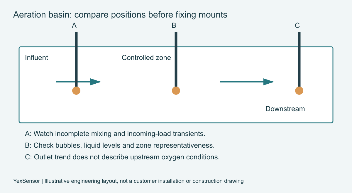
Aeration tank DO sensor placement: evaluate three locations
Survey positions before fixing brackets: compare synchronized reference readings, record water level and aeration state, and inspect bubble exposure. Revisit any point whose difference persists across operating states.
Near the influent, oxygen demand may change quickly as incoming wastewater enters the basin. This location can reveal disturbances but may be unsuitable as the only control point if the stream is not yet mixed. Avoid interpreting a local transient as a basin-wide oxygen shortage.
Within a controlled aeration zone, choose a position that reflects the mixed liquor governed by that zone. Review direct bubble contact with the sensing face and nearby hydraulic obstructions. There is no universally correct distance from every diffuser: tank geometry and the diffuser arrangement determine the field test.
Near the downstream end, a sensor can support an outlet oxygen trend or a final-zone control objective. It does not prove that upstream compartments received adequate oxygen. If upstream and downstream measurements answer separate decisions, retain separate tags instead of averaging them automatically.
Verified sensor evidence and what remains to be specified
YexSensor YEX-S1-RDO is a fluorescence DO sensor for projects within its confirmed operating limits. The table combines its official page with the supplied model-matched manual. Confirm the revision against the delivered configuration.
| Item | Verified specification / source | Procurement check |
|---|---|---|
| Range / accuracy | 0–20 mg/L; ±2% F.S. | Evaluate ±0.4 mg/L full-scale accuracy against thresholds. |
| Operating limits | 0–45 °C; pressure <0.2 MPa | Check maximum exposure, not only normal conditions. |
| Materials | POM and 316L stainless steel | Review chemistry, optical cap and cleaning compatibility. |
| Signal / supply | RS485 Modbus RTU; 12–24 V DC | Verify master, wiring and delivered register map. |
| Protection / installation | IP68; immersion | Keep the sensing face clear of sediment and bubbles. |
| Cable | 5 m standard; other lengths configurable | Confirm jacket material and extension arrangement. |
| Power | <0.3 W at 12 V in power-dissipation row | Manual also contains 0.2 W; confirm the design figure. |
The model-matched manual adds operating limits to the webpage summary. Its ±2% F.S. accuracy corresponds to ±0.4 mg/L on a 20 mg/L full scale, not ±2% of each reading. Evaluate that distinction near control thresholds. IP68 alone does not specify permissible installation depth or chemical compatibility.
The manual specifies POM and 316L components. Review wastewater chemistry and cleaning agents against all wetted parts, including the optical cap; the series name alone does not establish compatibility.
Compare immersion, bypass and additional measuring points
Direct immersion normally offers the shortest path between basin conditions and the sensing surface. It avoids a sample pipe, pump and drain, but the bracket must withstand the installation environment and allow retrieval without pulling on the cable. Protection against accidental impacts must not create a stagnant pocket around the probe.
A bypass can improve access when the basin is difficult to approach, but pumping and transport may change dissolved oxygen through gas exchange or sample residence time. Do not assume the bypass equals the basin. Compare simultaneous readings at commissioning and document the conditions under which the comparison remains meaningful.
Additional probes can support independent zones or verification. Adjacent sensors may share fouling and bubble exposure; redundancy needs a disagreement response, not just another input.
| Approach | When it fits | Decision boundary |
|---|---|---|
| Immersion within control zone | Mixed liquor governed by that zone | Compare reference readings and avoid direct bubble contact. |
| Downstream point | Outlet trend or final-zone duty | Do not infer upstream conditions from this point alone. |
| Bypass or extra point | Access or independent verification | Validate transport effects or define disagreement handling. |
Three equipment applications and their integration boundaries
The following are design examples, not claims about completed customer installations. Each connects a site challenge to a measurement arrangement and an observable project benefit.
Packaged biological treatment equipment
Field challenge: a compact basin has limited access and changing liquid levels. Integration approach: map the operating levels, provide a removable mounting assembly and confirm that the sensing area remains immersed during the intended measuring phases. Project value: the OEM can standardize the assembly while avoiding a probe that becomes exposed during normal operation.
Municipal aeration retrofit
Field challenge: an existing blower system serves several zones with different oxygen demand. Integration approach: associate each measurement with a defined zone and test how its trend changes during approved operating transitions. Project value: the integrator delivers signals with a clear control purpose, instead of a basin average whose relationship to individual actuators is uncertain.
Industrial wastewater with variable loading
Field challenge: production changes alter oxygen demand and may introduce fouling. Integration approach: keep process-event timestamps alongside DO, temperature and maintenance records, then review whether the proposed location distinguishes loading events from sensor contamination. Project value: commissioning evidence helps determine whether the next purchase should be another point, an improved mount or a different maintenance arrangement.

Install and commission the complete signal path
RS485 Modbus RTU support establishes an interface, not automatic interoperability. Obtain the register map for the supplied revision and verify address, serial settings, data type, byte order, units and any status information. Do not copy register addresses from another YexSensor model or assume a value represents mg/L rather than saturation percent.
Assign responsibility for bus wiring, grounding, shielding and power distribution. Check available voltage at the sensor under load, not only at the cabinet supply. Follow the device and host instructions for termination and biasing, and keep communication cables away from avoidable interference sources.
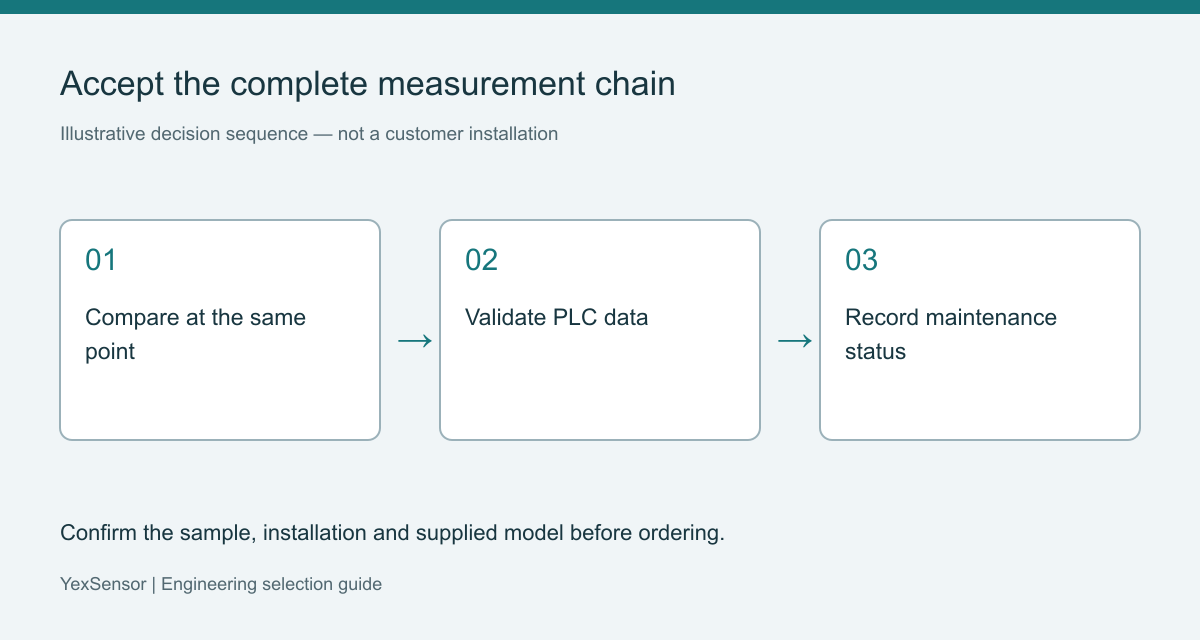
During acceptance, compare the host value with a suitable reference at the same location and time. Record temperature and the reference instrument's relevant compensation settings. A sample carried to a bench may exchange oxygen with air; a disagreement after transport is not automatically evidence of a failed online probe.
Test the host's response to lost communication and removal for service. Stale readings should not remain indistinguishable from fresh measurements. Agree the process response with the control designer; this article does not prescribe a universal blower fallback or oxygen setpoint.
Purchase scope and service access
Request the sensor, mounting details, cable arrangement, optical-cap service instructions and communication documentation as identifiable line items. Ask whether accessories are included rather than assuming the product photograph represents the delivery scope. Confirm replacement-part compatibility and the method for preserving calibration information during service.
Compare installation hardware and commissioning scope. Confirm destination, protective packaging, lead time and warranty terms; a low probe price cannot offset inaccessible maintenance.
Project configuration review
For the YEX-S1-RDO optical dissolved oxygen sensor, provide the basin drawing, diffuser layout, control objective, expected DO and temperature conditions, water chemistry, liquid levels, cable distance, host details and quantity. Identify who will install, clean and verify the probe. Send Your Project Requirements for a model and mounting review before you finalize the package.
Sources: official YEX-S1-RDO page and the matching model User Manual, technical specifications and installation/communication sections; reviewed October 23, 2026. Obtain configuration-matched documentation before ordering.
Frequently asked questions
Q1. What is the main rule for aeration tank DO sensor placement?
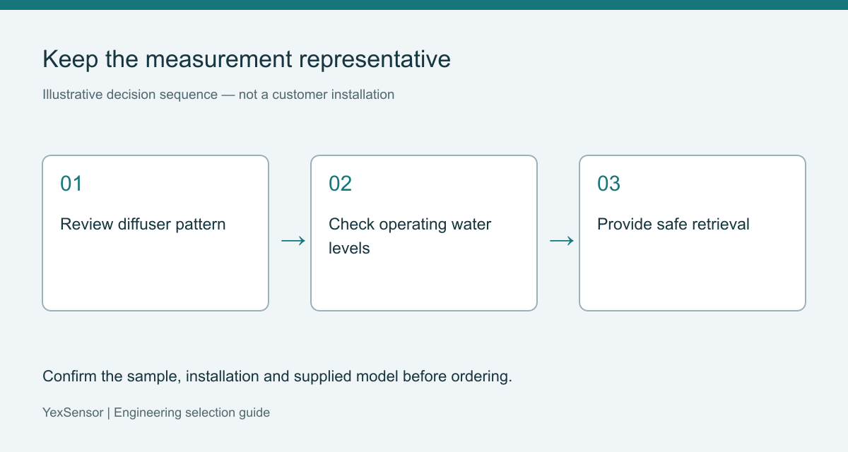
Place the sensor where it represents the zone and decision it serves. A convenient handrail is not enough if the nearby liquid is poorly mixed or dominated by local aeration. Before ordering brackets and cable, survey candidate positions during relevant operating states and document which actuator or reporting purpose each point supports.
Q2. Can bubbles affect an optical DO measurement?
Yes. Bubble contact and local aeration conditions can make a location unsuitable even when the optical sensor is functioning. Inspect the sensing surface and compare another representative position before changing calibration. Specify an accessible mount and include a bubble-exposure review in commissioning instead of assuming optical measurement eliminates installation effects.
Q3. Can YEX-S1-RDO connect to a PLC without a separate transmitter?
It can connect when the PLC or gateway provides a compatible RS485 Modbus RTU master and the required sensor power. Confirm register interpretation, wiring and communication settings for the delivered revision. A PLC with only analog inputs needs an appropriate interface solution; do not assume this model includes a 4–20 mA output.
Q4. What immersion depth should an integrator specify?
There is no single depth suitable for every basin. Select a representative level that remains submerged during the required measuring phases, then check the sensor's permitted immersion pressure and mounting constraints. Submit minimum and maximum water levels with the basin drawing so the supplier can review the complete installation rather than a nominal depth alone.
Q5. Is a bypass preferable when access is difficult?
Only if the sample remains representative of the basin and the additional transport effects are acceptable. A bypass improves service access but adds pumping, residence time and possible gas exchange. Compare it against an in-situ reference during commissioning, and include the pump, pipework, flow verification and drain in the procurement scope.
Q6. When should a project buy a second DO sensor?
Add a sensor when a separate zone, persistent spatial difference or defined verification requirement justifies another measurement. Two adjacent sensors do not automatically provide independent evidence because both can experience the same installation problem. Before purchasing, define tag names, disagreement alarms, maintenance responsibilities and the decision that the additional point will support.
Q7. What should the factory acceptance test cover?
Check the supplied model, cable, power requirements and communication documents, then confirm that the host interprets measurement data correctly. Simulate communication loss using an agreed procedure and verify status handling. Factory testing cannot establish basin representativeness, so reserve location, immersion and process-comparison checks for a documented site acceptance stage as well.
Q8. Which details make a quotation comparable?
Specify measurement points, mounting assemblies, cable lengths, host interfaces, required spare parts and commissioning responsibilities. Include water chemistry and operating conditions so material suitability can be reviewed. Ask each supplier to identify exclusions, delivery terms and warranty conditions; otherwise a bare probe quote may be compared incorrectly with a complete installed measurement package.
Q9. Does a stable DO trend prove the location is correct?
No. Stability can also occur in a sheltered or unrepresentative region, or when the host repeats stale data. Check the trend against operating events, a colocated reference and communication timestamps. Keep the point only when those checks support its intended purpose, and document the evidence before using it for automatic control.
Summary
Select an aeration measuring point by its control or verification purpose, then confirm representativeness across actual operating conditions. YEX-S1-RDO provides an optical RS485 option, but its range and interface cannot compensate for a poor location. Compare direct immersion with bypass sampling only after considering gas exchange, service access and transport effects. Verify host data and fault handling separately from field placement. A useful inquiry includes the basin layout, liquid levels, chemistry, measurement duty and installation responsibilities, allowing the sensor and mounting package to be assessed together.


