


 Chinese
 Spanish
 French
 Russian
 German
 Portuguese
 Indonesian
 Thai
 Vietnamese
 Arabic


Water quality monitoring for multimedia filters should begin with the decision your system must make: identify a failing vessel, protect downstream equipment, or release filtered water. Locate instruments around those decisions before selecting sensor quantities, ranges, or communication interfaces.

Water quality monitoring for multimedia filters: start with the control decision
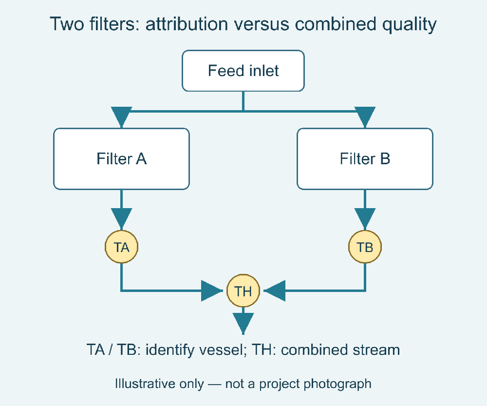
A common outlet measurement represents the combined stream, not necessarily each vessel. Consider two parallel filters: a header sensor supports a combined-water alarm; individual outlet sensors identify which filter changed. If the PLC must isolate one vessel automatically, header-only monitoring leaves that decision unsupported. This is an illustrative configuration, not a customer case.
Define the required response before drawing the instrument schedule. A trend used by an operator can tolerate a different architecture from an interlock that diverts water away from a membrane train. Neither architecture should be accepted solely because the selected probe has sufficient measurement range.
Separate water quality from hydraulic condition. Differential pressure helps assess resistance through a filter; turbidity responds to optical scattering in the sampled water. A favorable pressure reading does not establish particle removal performance, and a turbidity change alone does not identify a blocked bed.
Choose inlet, individual outlet, and common header measurements deliberately
An inlet reference is useful when source-water changes could explain shorter runs or altered outlet trends. It provides context, not a substitute for outlet verification. On a stable feed with limited project scope, an inlet instrument may have less immediate value than a well-installed outlet instrument.
Individual outlet points are justified when vessels operate independently and the system must identify which unit needs attention. A blended header can dilute a short excursion from one vessel. Sequential sampling reduces sensor count but introduces switching, flushing, and attribution requirements that must be addressed in the control design.
A common header point is useful for the final combined-water decision. Its position must account for bypass connections, chemical addition, and downstream mixing. If untreated bypass water can enter after the instrument, that instrument cannot represent the final delivered stream. Show these connections on the drawing rather than relying on equipment names.
| Measurement point | Decision supported | Procurement implication |
|---|---|---|
| Filter inlet | Distinguish feed changes from filter behavior | Select a range that covers credible feed excursions |
| Individual vessel outlet | Associate changes with a specific vessel | Budget isolation, service access, and separate PLC tags |
| Combined outlet header | Assess water delivered downstream | Locate after relevant blending and bypass connections |
| Temporary reference point | Investigate readings during acceptance | Provide a representative sampling connection and safe access |
Match the sensor configuration to maintenance and host requirements
The YexSensor YEX-S1-TS turbidity sensor is a candidate for digital monitoring points where planned manual cleaning is practical. The YEX-S2-ZS-8S turbidity sensor adds a cleaning brush and an optional analog output configuration. Those differences address servicing and integration; they do not remove the need for representative water at the optical window.
| Documented feature | YEX-S1-TS | YEX-S2-ZS-8S |
|---|---|---|
| Range options | 0–20 / 0–200 / 0–1000 NTU | 0–20 / 0–200 / 0–1000 / 0–4000 NTU |
| Digital interface | RS485 Modbus RTU | RS485 Modbus RTU |
| Analog interface | Not specified here | Optional 4–20 mA |
| Supply | 12–24 V DC | 12–24 V DC |
| Protection | IP68 | IP68 |
| Cleaning arrangement | Plan accessible manual cleaning | Built-in cleaning brush |
Ranges are separate order options, not proof of low-level performance. The S2 manual specifies ±3% of reading or ±1.5 NTU, whichever is greater, for its 0–20 NTU version. At 1 NTU, the ±1.5 NTU term governs: this cannot substantiate tight sub-NTU acceptance. Distinguish accuracy from resolution before approval.
For S2, the manual lists 0–60°C, pressure below 0.2 MPa, ABS and 316L housing, and a 5 m cable. Assess actual water chemistry and every fitting separately; these limits do not qualify the complete assembly. Approve S1-TS performance from its own configuration documentation.
Three project situations that need different layouts
Parallel pretreatment filters protecting reverse osmosis
The challenge is attributing an outlet excursion while maintaining production. A practical integration approach combines vessel identity and operating state with individual measurements where isolation is required. A final header point can support downstream protection. The value is traceability: operators can distinguish one vessel's return-to-service behavior from a change affecting the entire feed.
Do not equate turbidity with membrane fouling potential in every water matrix. Other acceptance tests may still be needed. Define what the turbidity signal will trigger and what additional investigation remains outside the skid's automatic logic.
Reuse-water filtration with changing solids loading
The challenge is variability across production batches, together with deposits on exposed optics. Assess whether a brush-equipped S2 configuration reduces the cleaning burden at the selected point. Record cleaning events and sample validity alongside the measurement. The value is a more interpretable operating record, not a promise that maintenance disappears.
Packaged filters with limited instrument budgets
The challenge is choosing which information to retain when every added point increases cost. A combined outlet sensor plus accessible individual sampling points may support a monitoring-only package. The integration boundary must remain explicit: it does not deliver continuous per-vessel fault localization. The value is a defensible scope that matches what the buyer actually needs.
Prevent installation errors from becoming apparent filter failures
For bypass measurements, document the source connection, tubing volume, intended flow, drainage arrangement, and any pressure reduction. Water reaching the sensor later than the process event can produce misleading comparisons between valve states and recorded turbidity. Transport delay and sensor response are different contributions to the total reporting delay.
For S2-ZS-8S, maintain more than 5 cm from sidewalls and more than 10 cm from the bottom, as its manual specifies. Include these clearances in chamber selection. Check air entry, incomplete filling, and settling before calibration; a convenient low pipe connection is not automatically representative.
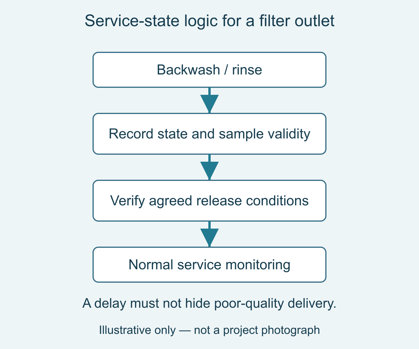
Backwashing, rinsing, and return to service deserve explicit states in the PLC. Store measurements during these states when useful, but distinguish them from normal delivery conditions. Any alarm delay or invalid-data rule should have a documented reason and should not conceal an actual poor-quality release.
Build an acceptance test around decisions, not just live numbers
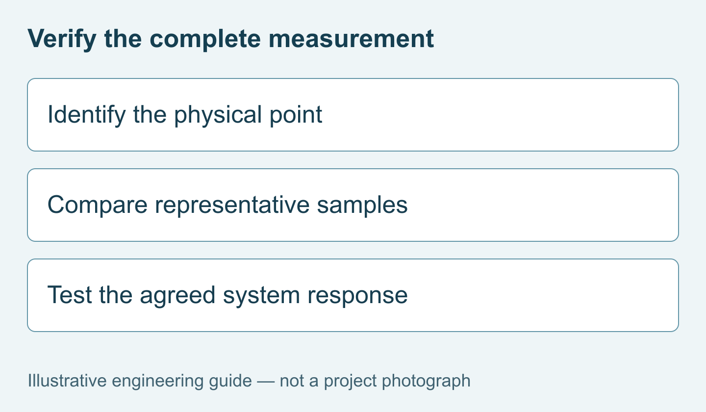
Start with tag identity: the physical vessel, sampling line, sensor address, and display label must agree. Then verify communication recovery, stale-data indication, and alarm behavior. A believable number on the HMI is insufficient if it belongs to the wrong vessel or remains frozen after a disconnected cable.
Compare online measurements with an agreed reference procedure under representative conditions. Record sampling location, time, filter state, cleaning history, and water appearance. Differences caused by timing or sample handling should be investigated before adjusting the instrument. For regulatory or contractual decisions, use the method and performance requirements specified by that project.
Test transitions as well as steady operation. Include one vessel leaving service, a rinse sequence, and restoration to normal delivery where safe and permitted. The objective is to establish whether the measurement supports the agreed decision throughout the operating cycle, rather than only during a convenient demonstration.
Define the package before requesting a quotation
Specify whether the purchase covers sensors only or also chambers, isolation valves, wiring, a controller, and commissioning. Ask the supplier to identify exclusions, maintenance items, documentation, delivery timing, and warranty terms in the quotation. Do not infer these commercial commitments from the presence of a product photograph.
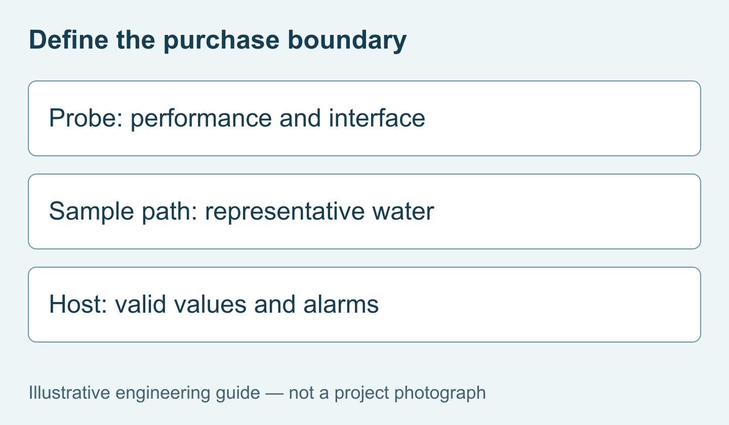
Send the filter arrangement, feed and outlet conditions, expected turbidity envelope, required action, number of independent vessels, host interface, sample routing, quantity, and delivery destination. For a brush-equipped option, review the YEX-S2-ZS-8S configuration and Send Your Project Requirements. This allows the quotation to address the measurement package rather than an unspecified probe.
FAQ
Q1. Does every multimedia filter need an online turbidity sensor?
No. Individual instruments are justified when the project needs continuous vessel-level identification or independent release decisions. A common header instrument may be adequate for combined-water trending. For water quality monitoring for multimedia filters, specify the required response first, then compare the cost and limitations of continuous points, sequential sampling, and manual checks.
Q2. Can differential pressure replace outlet turbidity monitoring?
No. Pressure difference and turbidity answer different questions about the filter. Hydraulic resistance does not establish the optical quality of the outlet stream. If downstream protection depends on particle-related changes, assess a suitable water-quality measurement separately. Include both signals in the operating review when the project requires hydraulic diagnosis as well as quality assessment.
Q3. How should Modbus readings be associated with filter operating states?
Associate each address and PLC tag with its physical measurement point, then record the vessel state with the reading. Include communication validity and timestamps. During rinsing or cleaning, the value may need different interpretation from normal service. Agree these rules during integration rather than asking operators to infer them from unexplained trend spikes.
Q4. When is a cleaning-brush sensor worth specifying?
Consider YEX-S2-ZS-8S where deposits require frequent cleaning and access is costly. Its brush addresses deposits, not bubbles or sampling errors. Its manual requires more than 5 cm sidewall and 10 cm bottom clearance. Check chamber space and maintenance costs against an accessible S1 installation before specifying the brush-equipped option for a filter skid.
Q5. Should the inlet and outlet use identical ranges?
Not necessarily. Inlet excursions and the outlet decision level can require different performance envelopes. Standardizing hardware simplifies spares, but should not obscure the measurement requirement. Ask for model-specific range and accuracy information for each point, and evaluate outlet performance at the relevant decision level instead of selecting only by the largest expected inlet reading.
Q6. Is one shared sensor suitable for several filter outlets?
It can be, if sequential information meets the project's response requirement. Switching needs sufficient flushing, clear point identification, and verification that residual water from one line does not affect the next. Include valves, control logic, downtime, and maintenance in the comparison. Do not describe a sequential system as simultaneous continuous measurement of every vessel.
Q7. What information makes supplier quotations comparable?
Provide the instrument count, ranges, interface, operating conditions, mounting concept, and required package boundary. State whether sampling hardware and commissioning are included. Request separately identified accessories and maintenance items. Two quotations for the same sensor model can represent very different delivered systems if one excludes chambers, cables, PLC work, or acceptance testing entirely.
Q8. Can a filter-monitoring sensor certify drinking-water compliance?
Not by model name or protection rating alone. Compliance depends on the applicable measurement method, performance, installation, verification, and regulatory requirements. For projects involving drinking-water release, obtain the specified evidence and acceptance procedure before purchase. Keep operational trend monitoring distinct from any formal compliance claim in both the technical specification and the customer proposal.
Q9. What should the factory acceptance test demonstrate?
It should demonstrate the agreed signal paths, tag mapping, fault indications, and relevant operating-state logic. Where suitable water testing is included, document its conditions and limitations. Site sampling behavior still requires site verification. Make the distinction explicit in the contract so a successful electrical test is not mistaken for complete validation of filtration performance.
Summary
Choose multimedia-filter monitoring points according to the decisions they must support. Individual outlets provide attribution; a common header represents the combined stream; an inlet reference explains changing feed conditions. Match S1 or S2 configurations to maintenance and interface needs without treating a brush, IP68 rating, or display resolution as proof of complete suitability. Verify sample routing, optical installation, operating-state logic, and reference comparisons. A useful quotation starts with the filter arrangement, decision level, expected water conditions, required interfaces, and a clearly defined delivery boundary.


