


 Chinese
 Spanish
 French
 Russian
 German
 Portuguese
 Indonesian
 Thai
Thai Vietnamese
 Arabic

Direct Answer: How Should an RS485 Water Quality Sensor Be Wired?
Wire the sensor power and RS485 pair exactly as shown in the manual for the ordered model, then configure a unique device address and matching serial settings before connecting the PLC or SCADA network. Do not assume that A/B labels, wire colors, default address, baud rate, parity or register layout are identical across suppliers or models.
A successful installation is a complete data contract: power, polarity, bus topology, shielding and grounding, address, baud rate, parity, function code, register, data type, byte order, unit, scaling, status handling and timeout behavior must all agree.
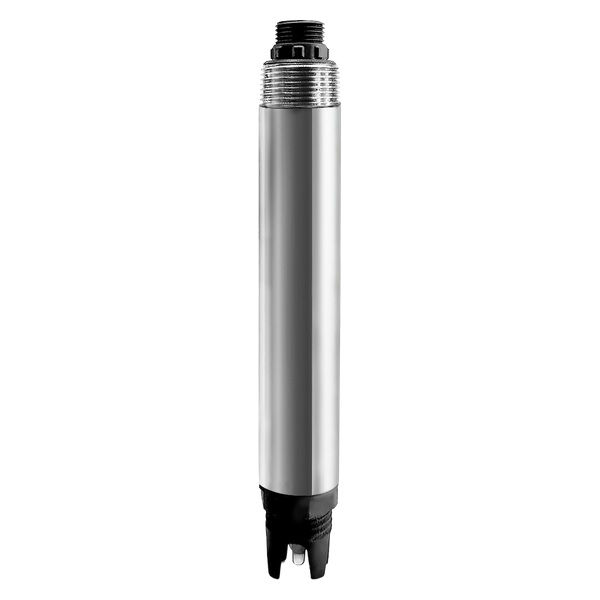
Buyer Risk: Treating RS485 as Plug and Play
RS485 defines an electrical layer, not a universal water-quality register map. A correctly powered probe can still return no data because of reversed polarity, duplicate addresses or serial mismatch. It can also return a believable but wrong number when the PLC uses the wrong register offset, data type, byte order, unit or decimal scaling.
| Layer | Confirm before wiring | Typical failure | Acceptance evidence |
|---|---|---|---|
| Power | Voltage, polarity, consumption, isolation and common reference | No startup, resets or damaged device | Measured supply at the sensor under load |
| RS485 bus | A/B definition, topology, shield, ground and termination requirement | No response, intermittent frames or noise | Stable communication at intended cable route and device count |
| Serial settings | Address, baud rate, parity, data bits and stop bits | Timeout or collision | Commissioning sheet for every device |
| Modbus data | Function, register, offset convention, data type, byte order, unit and scale | Plausible but incorrect engineering value | Local value equals PLC and SCADA value |
| Fault handling | Timeout, stale-data limit, invalid range and maintenance mode | Frozen value drives control | Witnessed fault and recovery tests |
Use the Exact Model Manual
Record the full model and hardware or firmware revision before panel fabrication. Use only the wire definition and Modbus map supplied for that item. If a distributor, OEM panel builder or EPC receives a revised sensor, repeat the document check instead of copying settings from an earlier job.
The YEX-S1PRO-PH example is published with 12-24 VDC power, RS485 Modbus communication, a 0-14.00 pH range, 0.01 resolution, automatic temperature compensation and a 5 m four-core shielded cable. Those values support this example only and must not be transferred to another water-quality model.
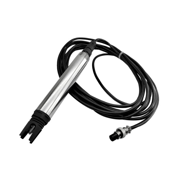
Panel and Bus Design Checklist
Use a trunk topology appropriate to RS485 and keep stubs short according to the project standard and device documentation. Route low-level communication away from variable-frequency drives, contactors and high-current conductors. Apply shielding, grounding, surge protection and termination according to the complete system design.
Calculate voltage drop to the farthest sensor under worst load, especially at remote stations. Define cable type, junction boxes, connector protection, isolation boundary and the party responsible for field splices. Label every device address and cable at both ends.

Modbus Data Contract for PLC and SCADA
Create a point list that states the register reference, protocol address, function code, data type, byte order, scale, unit, valid range, poll interval, timeout, data age and fault action. Store the source manual revision with the PLC project.
SCADA should display the measured value and its quality state. If communication is lost, mark the point bad or stale and prevent uncontrolled use of the last value. Trend communication status and maintenance events with the process data.
Bench Test Before Field Installation
Power one sensor with a current-limited supply, confirm the default communication settings from the manual and read a known register with a trusted Modbus master. Change the address only through the approved procedure and record it. Add devices one at a time so duplicate addresses or polarity differences are found early.
Compare the sensor or local-tool value with the PLC engineering value. Verify decimal position, sign, temperature and status fields. Simulate timeout, power interruption and reconnection before the panel leaves the workshop.

Field Commissioning and Troubleshooting
| Symptom | Check first | Do not do first |
|---|---|---|
| No device responds | Power, common reference, master settings and A/B definition | Rewrite every address or register |
| One device is missing | Its power, address, connector and local bench response | Change the entire bus configuration |
| Intermittent data | Topology, shield, ground, termination, noise and voltage drop | Increase polling speed |
| Wrong but stable value | Register offset, data type, byte order, unit and scale | Calibrate the wet sensor |
| Value freezes | Timeout, data age and PLC quality logic | Continue automatic control from the last value |

RFQ and Acceptance Checklist
Submit sensor models and quantities, parameters and ranges, cable lengths and routes, power, enclosure and surge requirements, PLC or gateway brand, available ports, required baud and parity, network device count, local display, SCADA point list, protocol documents, environmental conditions, commissioning location and acceptance tests.
Review the YEX-S1PRO-PH RS485 pH sensor, RS485 Modbus water-quality integration FAQ and relevant product manual, then Send Your Project Requirements for a model-specific wiring review.
FAQ
Q1. Are RS485 A and B labels universal?
No. Label conventions can differ. Follow the exact device manual and confirm with a bench test instead of relying on color or a previous supplier.
Q2. Can several water-quality sensors share one RS485 bus?
Yes, when every device has a unique address and the electrical load, topology, serial settings, polling and isolation fit the network design.
Q3. Does every Modbus sensor use the same register map?
No. Registers, offsets, data types, scaling and status fields are model-specific. Store the correct manual revision with the PLC program.
Q4. Where should the cable shield be grounded?
Follow the approved panel and site grounding design plus device documentation. Avoid improvising multiple shield bonds that create unwanted current paths.
Q5. When is RS485 termination required?
It depends on bus length, speed, topology and device guidance. Place termination only as required by the engineered bus, not automatically at every sensor.
Q6. Why is the PLC value wrong when communication is stable?
Check register offset, function code, signed or unsigned type, floating-point format, byte order, unit and decimal scaling before touching calibration.
Q7. What should happen during communication loss?
Mark the point invalid or stale, alarm the operator and move control to the defined conservative mode. Do not treat the last value as current indefinitely.
Q8. Should addresses be changed in the field?
Prefer a documented bench procedure before installation. If field changes are necessary, isolate the target device and record the final address.
Q9. What must a supplier provide for integration?
Require the exact wiring diagram, power data, serial defaults, address procedure, register map, data formats, status behavior and current manual.
Q10. What should FAT and SAT prove?
FAT should prove mapping and fault logic. SAT should prove installed power, bus stability, local-to-SCADA agreement, alarms, recovery and maintenance ownership.
Summary
RS485 water quality sensor wiring succeeds when the electrical bus and Modbus data contract are both verified. Use the exact model manual, test one device before building the network, document addresses and registers, expose stale or invalid data in PLC/SCADA and include cable, power, protocol, fault behavior and acceptance evidence in the RFQ.



