


 Chinese
 Spanish
 French
 Russian
 German
 Portuguese
 Indonesian
 Thai
 Vietnamese
 Arabic


Dissolved oxygen probe placement in aeration basins should reflect which air valve the reading will control. During restart, measure in the returning lane before its water mixes with the discharge from lanes already operating. Keep airflow under the approved restart procedure until the local signal is current, the probe is correctly immersed and a reference check supports the reading. The oxygen trend can support transfer to automatic control. It cannot establish treatment performance on its own.
Can a shared outlet reading verify the restarting lane?
A common outlet probe can show a steady value while one returning lane has little circulation. The running lanes dominate the blended measurement. The reverse problem arises beside a diffuser, where a probe sees a local plume that is unrepresentative of the zone being controlled. Either installation can give a functioning controller the wrong information for adjusting air.
Start the instrument schedule with a lane diagram. Mark the inlet distribution, zone supplied by each air valve, proposed probe depth and point where flows rejoin. Follow the physical cable back to its controller channel. A common blower arrangement does not necessarily imply a common oxygen condition. If one lane is out of service, confirm how the remaining branches receive air and which controller will own the common equipment during transfer.

Instrument limits for dissolved oxygen probe placement in aeration basins
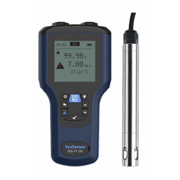
The YEX-S1-RDO probe measures oxygen in the water. Allocate a separate instrument input for branch airflow if actual air delivery must be proven during restart.
| Model | Published specification | Decision at this installation |
|---|---|---|
| YEX-S1-RDO | 0–20.00 mg/L | Check the site operating and alarm values against this concentration span. |
| YEX-S1-RDO | Optical fluorescence | Provide inspection access to the sensing surface after downtime. |
| YEX-S1-RDO | RS485 Modbus RTU | Assign lane identity, units and freshness checks at the controller. |

Compare feedback locations
| Arrangement | Question answered | Selection criterion |
|---|---|---|
| Common outlet only | Combined trend | Retain for overview. Add a local check before assigning a lane-specific control action. |
| Fixed local probe | Continuous feedback during service | Choose a location representative of the controlled zone and accessible during cleaning. |
| Portable survey | Find a representative location or verify a restart | Record depth, time and blower state. A spot survey leaves intervals without observations. |
A restart survey should preserve the operating context of every reading. Record lane identity, water level, elapsed time since refilling, local flow condition and blower or valve state. If the portable instrument is moved between positions, note the sequence and allow the reading to stabilize under its own operating instructions. Otherwise a difference attributed to probe position may simply reflect changing aeration while the operator walked along the lane.
A lane returning after maintenance
Consider a lane drained for maintenance. A probe left on its bracket may be out of water, and the controller may still display its last valid reading. Mark the lane unavailable during maintenance. When water returns, inspect the sensing head, verify immersion and compare a portable reading taken at the same depth. Restoring communication proves only that a device is answering.
Before deciding that the fixed probe is biased, compare like with like. Use the same concentration unit, verify both instruments under their respective service procedures and compare at the same depth and time. If the reference follows the fixed probe during a local change, investigate the actual process. If it diverges under stable colocated conditions, inspect the optical surfaces and the host scaling before authorizing an offset or replacing the probe.
For routine siting and optical-cap maintenance, see the aeration basin placement and cleaning guide.
At restart, give the operator three distinct sign-offs. First, maintenance returns the probe to its marked depth in the refilled lane. Next, instrumentation confirms that a fresh fixed reading agrees with the colocated reference within the site tolerance. Finally, operations witnesses the transfer from manual air delivery to the automatic loop. Record the lane and timestamp at each step so that passing the first check cannot be mistaken for authority to perform the last.
Which mounting point should go on the purchase drawing?
For a plug-flow lane, survey the inlet region, middle and outlet under comparable loading before fixing the bracket. For a nominally mixed basin, first test whether the long axis still has an oxygen gradient. Procurement can provide two accessible mounting positions for a movable probe when the best feedback point changes with operating mode. That arrangement measures one position at a time.
| Observed condition | Project check |
|---|---|
| Air header serves several lanes | Header airflow indicates total delivery. If the acceptance test must establish delivery to the restarting lane, specify branch feedback or an agreed independent test. |
| Several possible DO locations | Record position, depth, lane state and airflow together. Select the point that represents the zone the valve can actually influence. |
| Air command changes before DO responds | Trend command, measured branch flow and DO on the same clock. Establish the observed lag during the test before retuning the loop. |
How to check probe depth and restore automatic air control
Walk the signal from probe to PLC trend to airflow command. Confirm that lane B really drives the lane B control calculation. Establish how the operator distinguishes a flat but valid DO trace from a value which has stopped updating. If several lanes share a blower, review the effect of one control loop on the others before testing an automatic transfer.
A practical acceptance sequence starts with a dry simulation of a missing probe, then a wet comparison with a reference instrument, followed by observation during a controlled airflow change. Use the process owner’s limits during testing. Record measured air delivery separately from blower command where available. A command that changes without a delivered-air change points to a different investigation from a probe that disagrees with a paired reference.
Agree a fallback state with the process owner for the time when the probe is removed. Document the responsibility for air supply, the visible maintenance indication and the conditions for leaving fallback. During acceptance, demonstrate removal and restoration in a controlled mode. Verify that the operator can observe a fresh measurement before control resumes and that the return to automatic operation does not unexpectedly transfer authority over adjacent lanes.

Specify probe access and the transfer to automatic control
List the number of independently controlled lanes, water levels, proposed mounting locations, cable distances, blower arrangement, normal and restart modes, availability of a portable reference and access for cleaning. Require a documented fallback for maintenance or loss of signal and identify who authorizes return to automatic control.
Ask the supplier to quote a serviceable installation. A bracket that requires personnel to reach over a basin or disturbs the selected depth every time the probe is cleaned creates an operational burden. Review retrieval from the approved access point, cable strain relief and repeatable positioning with the site team. Record the final location on the drawing together with the reference point used for future wet comparisons.
Which signals should be logged at transfer?
Define the transfer of control as a witnessed event. The commissioning sheet should identify the lane, the air valve, the controller operating mode, the local DO value and its timestamp, the reference reading and any active inhibits. Capture the last manual air command and the first automatic command. A sudden change at transfer can come from controller initialization or a mismatched output scale even when the oxygen measurement itself is accurate. Include this transition in the controls scope instead of leaving it to the instrument supplier.
A useful diagnostic exercise compares two observations during an approved change. If measured airflow follows the command and the portable and fixed oxygen readings move together, investigate the process response before replacing the probe. If airflow fails to follow its command, check the air distribution equipment. If both air signals are consistent but only one oxygen instrument moves, repeat the local comparison and examine the measurement channel. These observations guide the next test; none alone establishes a biological cause.
Procurement can also decide whether to provide a permanent reference location. A marked safe access point at the installed depth makes verification repeatable across operators and shifts. Mark the location on the drawing and identify the water level below which that comparison becomes invalid. If the service platform cannot accommodate both instruments at once, agree an alternative verification method with operations before the mounting hardware is fabricated.
| Acceptance record | Fields to complete on site |
|---|---|
| Lane identity | Lane: ___ / probe depth: ___ / water level: ___ / timestamp: ___ |
| Independent check | Fixed DO: ___ mg/L / reference DO at same depth: ___ mg/L |
| Transfer evidence | Last manual air command and unit: ___ / first automatic command and unit: ___ / measured branch airflow and unit, if available: ___ |
| Reference agreement | Difference between paired readings: ___ mg/L / site tolerance: ___ mg/L / within tolerance: yes or no |
| Control handover | Air valve ID: ___ / active transfer inhibits: ___ / remained in manual or transferred to automatic: ___ / witness and time: ___ |
Project data for instrument selection
Send the lane drawing, intended probe locations, restart modes and alarm response requirements.
Frequently asked questions
Q1. Can the common outlet confirm oxygen recovery in a restarting lane?
A1. A mixed outlet measures the combined discharge and can mask one weak lane. Use it as a plant trend, then verify the returning lane at a defined local point before allowing a lane-specific action. Compare the two readings alongside lane flow and blower status. Agreement after mixing alone cannot identify a problem confined to one branch.
Q2. Why check a sensor that is already communicating?
A2. Communication establishes that the controller can read a device. It does not establish immersion, cleanliness or correct lane assignment. Following downtime, inspect the sensing head, verify water level and compare a portable measurement at the same location. Record the device address with the physical lane so a valid reading from another channel cannot pass the restart check.
Q3. What does a falling local DO trend indicate?
A3. It indicates a change in oxygen concentration at the measurement location. Possible explanations include changing demand, reduced circulation, altered air delivery or a contaminated sensing surface. Check delivered airflow and a colocated reference before changing the control objective. Keep process samples available for the operator responsible for assessing biological recovery and downstream treatment quality.
Q4. How should diffuser location influence dissolved oxygen probe placement in aeration basins?
A4. Select the position by surveying representative water under the intended operating conditions. Direct exposure to a concentrated plume or attached bubbles can distort the significance of the reading. Compare several locations and depths during a controlled test, then specify the bracket position and withdrawal clearance on the drawing so maintenance staff can reproduce the selected position.
Q5. Is a portable meter enough for the restart?
A5. A portable meter is useful for mapping the lane and checking a fixed probe after refilling. It leaves gaps between visits and does not provide a continuous control signal. If airflow adjustment relies on continuous feedback, include a local fixed channel and use the portable instrument as an independent check with a documented comparison procedure.
Q6. Should every lane have its own probe?
A6. Base the count on the independence of water flow and airflow control. Lanes with separate air valves or different loading may need distinct feedback. Where one measurement is proposed for multiple lanes, test its coverage during unequal operating conditions. Include the instrument inputs and service access for any extra locations justified by that survey.
Q7. What should a restart acceptance test demonstrate?
A7. Show that the correct lane is selected, the probe is immersed, the reference comparison is acceptable and the controller responds properly to stale data. Then test transfer between manual and automatic operation under approved conditions. Keep a time record of probe readings, air commands, available feedback and lane status so unexpected changes can be traced.
Q8. Which spare parts and services belong in the quotation?
A8. Identify the exact probe and optical cap configuration, mounting components, cable length, cleaning access and reference equipment. Separate initial integration from ongoing inspection and cap service. Request the delivered manual and register map with the quotation so maintenance staff can restore the channel correctly after replacement and repeat the wet acceptance check before returning to automatic operation.
Summary
For a lane returning to service, place the dissolved oxygen probe in the water influenced by that lane's air valve, upstream of mixing with other lanes. A common outlet can show a steady oxygen trend even while the restarting lane receives too little air. Choose the bracket location from measurements made at candidate points under comparable loading, and mark the selected depth so maintenance staff can reproduce it after cleaning.
The YEX-S1-RDO is a candidate where its 0–20.00 mg/L range covers the operating and alarm values and the controller accepts RS485 Modbus RTU. Before handing control back to automatic operation, compare the fixed probe with a reference instrument at the same depth and time. If the readings agree but oxygen fails to respond to a valve command, check measured branch airflow where available. A blower command alone cannot confirm delivery to that lane.
The RFQ should identify each independently controlled lane, its valve, water levels, probe access and the required response to a lost signal. At handover, record the last manual command, first automatic command and the person who authorized the transfer. This gives operators a starting point for diagnosing an abrupt airflow change on the next restart.


