Chinese
 Spanish
 French
 Russian
 German
 Portuguese
 Indonesian
 Thai
 Vietnamese
 Arabic


Specify a submersible water level sensor for each observation well using the expected water column above the probe, the lowest water elevation that must still be observed, and a permanent mark for manual checks. Put those three elevations on one drawing. A pressure reading represents water above the diaphragm. The dewatering decision usually concerns groundwater elevation or drawdown relative to a baseline.
Decide which water level controls the work
A contractor pumping an excavation may watch the sump and several screened observation wells. The sump tells the crew about water collected at the pump. A well outside the excavation can reveal a different groundwater response. Assign each monitoring point its own purpose before pricing a fleet of identical transmitters. Ask the responsible engineer which wells inform excavation operations, which are observation points for neighboring assets, and which require a record through pump shutdown and recovery.
Give each well a permanent identifier, a physical measuring mark and a signed convention for the reported value. Depth below casing increases when groundwater falls. Water-surface elevation decreases. Confusing those conventions can reverse an alarm even when every instrument is accurate. Have the field technician point to the actual measuring mark and the controls technician display the same well and unit on screen.

Check the submersible water level sensor against the well drawing
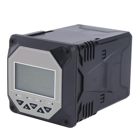
The YEX-HY-LLT-01 submersible level transmitter has a published probe diameter of 26.8 mm, a 10–30 VDC supply and RS485 Modbus RTU output. The manufacturer lists the measuring range as project-specific. Ask for the ordered span, pressure reference, cable arrangement and compatible fluid before placing the order. A nominal casing diameter does not establish clearance past joints, a locking head, existing cables or a manual tape.
| Drawing or specification | Acceptance question |
|---|---|
| Lowest water surface and sediment depth | Can the diaphragm remain submerged with room below it throughout pumping and recovery? |
| 26.8 mm probe body | Will the complete assembly pass through the narrowest opening and leave a route for independent readings? |
| RS485 and 10–30 VDC | Can the logger decode head, flag a disconnected probe and supply the required voltage at the farthest well? |
Compare the well, sump and discharge measurements
A pressure probe can be considered for a narrow observation well after the assembly clearance and manual measurement access have been checked. At an open sump, non-contact radar may be an alternative if the engineer needs the sump surface. Its reading still describes a different point from the observation well. Keep the sump and well elevations on separate tags. When the pump starts, note which tag responds first and what the other was expected to do. A different timing response alone provides no evidence that one instrument is faulty.

If engineers intend to interpret water-level change against pumping rate, include an independent discharge measurement. For an open outlet, assess whether an open-channel instrument has suitable geometry, flow conditions and a surveyed section. A closed discharge pipe needs a meter suitable for that pipe. Record pump changes, outages and rerouting with the water levels. A smaller drawdown on the second shift can reflect changed pumping or changing groundwater conditions; the probe alone cannot identify which occurred.

Evaluate drawdown and the required project record
Calculate the range from the diaphragm elevation
Consider an illustrative well with a measuring mark at elevation 105.00 m and a probe diaphragm at 95.00 m on the same project datum. Before pumping, a tape measurement finds water 3.00 m below the mark. The water elevation is 102.00 m, and the freshwater head above the diaphragm is 7.00 m. When the water is 6.00 m below the mark, the water elevation is 99.00 m, the head is 4.00 m and the drawdown from the stated baseline is 3.00 m. Store head, elevation and drawdown in separate fields with units. For an open well in approximate hydrostatic equilibrium, divide water pressure above local atmospheric pressure by water density and gravitational acceleration to obtain the head above the diaphragm. With an absolute sensor, subtract a time-matched barometric reading in the same pressure units before conversion. Check whether the logger has already applied this correction.
A range chosen from the 3.00 m expected drawdown alone would miss the initial 7.00 m head. Determine the highest credible recovered water level as well as the lowest pumped level. Select a usable span covering the associated pressure, with allowance appropriate to the selected instrument and project. Check that the probe stays submerged at the lowest required observation and sits clear of settled sediment. If both conditions cannot be met in the available well, document the unobservable interval and resolve the installation before approving the purchase.
What London Crossrail required contractors to record
On the London Crossrail project, the environmental works specification required contractors to keep records of water pumped at major dewatering sites with deep-aquifer wells or where a discharge consent required them. For an observation-well installation, this illustrates a practical procurement decision: who will record extraction as well as groundwater response? Include separate tags for discharge and well level, then agree how to synchronize their clocks. See Crossrail Works Information, section 21.11.6.1.
Run a baseline, pumping and recovery check
Before starting the pump, use the marked casing reference to take a manual depth reading, noting the time and the name of the well. Compare the derived elevation with the installed instrument and its recorded suspension position. Verify whether the selected pressure design references atmosphere through a vent or requires a separate barometric measurement. Protect a vent termination as the manufacturer directs. For an absolute-pressure design, verify how barometric correction is made and how the logger flags missing pressure data.
During a planned change in pumping, record the command time and actual pump status. Choose the logging interval with the engineer responsible for the expected transition. An instrument's internal sampling rate does not determine how often the field logger stores or uploads data. Check the local archive through a communications interruption. The recovered data should retain their original measurement times. A dashboard line drawn between two surviving values can obscure the time the well actually crossed an action elevation.
At pump shutdown, collect a second independent tape reading during recovery and match it to the sensor timestamp. If the crew moves the cable clamp to access the well, measure and record the new diaphragm position before using the next result. Lowering the probe changes indicated head even if groundwater elevation stays constant. Preserve the original data and the installation change time so the engineer can distinguish an offset correction from a real water movement.
Specify handover at each temporary site
Ask bidders to identify who supplies the suspension hardware, cable protection, power, logger, barometric reference where needed and independent checking equipment. Specify how a station will be moved, relabeled and verified if the excavation advances. Require the commissioning record to include the baseline tape reading, instrument serial number, surveyed measuring mark, installed diaphragm elevation, tag units and a witnessed loss-of-signal test. The project engineer should set action levels and specify the response to missing readings for each observation point.
For field guidance on permanent measuring points and repeat observations, see the USGS guidance on permanent measuring points, steel-tape measurements and submersible pressure transducers. Use the project survey datum and the instrument-specific installation procedure alongside the field method.
Project requirements
Provide the well drawing, casing clearance, datum, expected high and low groundwater elevations, sediment depth, cable route and logger interface. Include the required span and pressure reference for the YEX-HY-LLT-01 transmitter.
Frequently asked questions
Q1. How do we convert probe head to groundwater elevation?
A1. Establish the diaphragm elevation on the same datum as the manual measuring point. Add the applicable pressure-derived water head above the diaphragm to that elevation. Confirm the pressure reference, assumed water density and unit conversion used by the logger. Compare the resulting elevation with a tape observation at the same time before accepting the channel.
Q2. Does the full well depth determine the pressure range?
A2. Size the span around the greatest credible water column above the installed diaphragm, including recovery when pumping stops. Well depth matters for access and installation but does not by itself establish the head at the probe. Provide both the proposed suspension elevation and the highest expected water elevation when requesting the range.
Q3. What happens if the water drops below the probe?
A3. The instrument loses the submerged water column needed to follow a further decline. Mark the period as outside the installed measurement coverage and take an appropriate independent observation if it is needed for the project decision. Review sediment clearance and well depth before lowering the probe to capture a subsequent event.
Q4. Should we order a vented or absolute-pressure instrument?
A4. Choose after identifying how atmospheric pressure will be handled throughout the deployment. A vented configuration needs a protected working vent path. An absolute-pressure installation needs a suitable barometric observation and a documented correction. Ask the supplier to confirm the ordered reference design and demonstrate the recorded groundwater response during a stable-water comparison.
Q5. Can a level instrument at the sump replace the observation well?
A5. Decide which location represents the engineering decision. A sump instrument reports the water collected at the excavation pumping point. A screened well observes head at its own location and screened interval. Use separate identifiers and comparable elevation references when both matter, and ask the responsible engineer to approve any proposed change in observation coverage.
Q6. How should we compare a tape reading during rapid drawdown?
A6. Record the time of the manual observation and use the same casing mark every time. Select the sensor record corresponding to that observation, allowing for the actual logger interval and the rate of level change. A reading several minutes later can show a real decline and should not automatically become an offset adjustment.
Q7. What should commissioning demonstrate before excavation advances?
A7. Witness a baseline comparison, a pump-state transition and a disconnected instrument. Check the sign and units of drawdown at the operator display and ensure that unavailable data remain identifiable in an export. Retain the installed depth and logger configuration with the station identifier so a replacement crew can repeat the test.
Q8. What records are needed when moving a probe to another well?
A8. Close the old installation record with its final time and manual check, then create a new station record for the receiving well. Include its measuring mark, datum, diaphragm elevation, serial number and baseline. Verify the first reported elevation independently so a change in suspension or reference point cannot masquerade as groundwater recovery.
Summary
Purchase the instrument against the expected head at its installed elevation. Confirm well clearance, pressure reference, cable support and logger behavior on the actual site. Pair the installation with a permanent manual measuring mark and a pump-event record so engineers can interpret drawdown, recovery and missing observations across the temporary works.