


 Chinese
 Spanish
 French
 Russian
 German
 Portuguese
 Indonesian
 Thai
 Vietnamese
 Arabic


Before transferring an ORP alarm setpoint to a replacement probe, identify the reference system behind each millivolt reading and compare both probes in the same process water. Verify the replacement signal at the PLC and test whether it gives the intended warning during a real operating change. A matching connector or measuring range alone cannot establish that the old alarm still makes the right decision.
Why did the alarm move after a probe change?
Consider a plant replacing the ORP probe on a treatment reactor. The archived alarm was established on the old instrument, and the controls technician proposes copying its millivolt setting into the new channel. Three different things could change the outcome: the replacement electrode can report a different potential in the same water, it can respond at a different speed, or the PLC can interpret the transmitted value incorrectly. Each calls for a different correction.
Start by recording what the old alarm actually did. Was it an advisory warning that called for an operator sample, a permission to proceed to another batch step, or an input to automatic dosing? Record the alarm direction, persistence time, deadband, data filtering and action on an invalid reading. Include the site's independent test for the process condition that matters. A project cannot verify a transferred threshold if nobody can say which action it is supposed to protect.
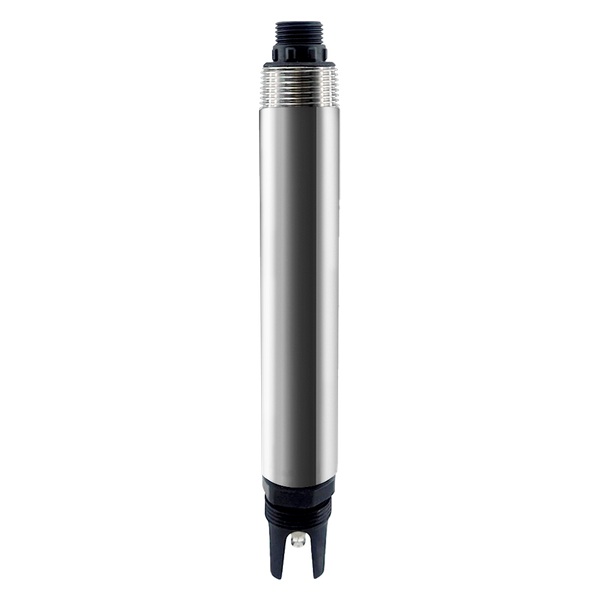
Which specifications matter for an ORP probe replacement?
ORP is a potential difference between a measuring electrode and a reference system. Ask both suppliers for the measuring surface, reference electrode, electrolyte and reporting convention of the actual ordered configuration. Where an instrument applies an adjustment or reports relative to another reference scale, identify that setting. A document describing a typical electrode does not identify the construction of either unit in your panel. Hamilton's explanation of ORP measurement.
The YEX-S1PRO-ORP product specifications identify the supported output options and published instrument performance. Use these figures to screen the proposed hardware. Ask separately for the delivered reference details, behavior of the temperature channel and applicable verification procedure before approving the comparison.
| Item | Published YEX-S1PRO-ORP specification | Replacement decision |
|---|---|---|
| Range | −2000 to +2000 mV | Include both the normal values and the process alarm region. |
| Accuracy | ±20 mV | Assess whether the installed system can distinguish the change that matters. A wider span does not improve that margin. |
| Response | 30 s published response time | Verify actual alarm timing with mounting and filtering included. |
| Output | RS485 Modbus RTU or optional 4–20 mA, select one | Order the version compatible with the receiving hardware and verify the signed millivolt scale. |
| Installation | NPT 3/4 immersion, 0–50 °C non-freezing, pressure below 0.2 MPa | Check the complete holder and exposure conditions before reusing old hardware. |
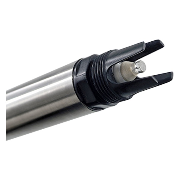
Choose how to bridge the old and new records
Where access permits, operate the old and new probes side by side at equivalent depth in the same mixed water. Give the replacement its own temporary tag and archive both readings. This arrangement permits simultaneous comparison through an operating transition. Ensure neither holder interferes with flow around the other sensing surface and inspect both electrodes in their as-found condition before changing calibration.
A portable instrument can be a useful comparator when the old device is already unavailable. Check its reference basis and response in the prescribed verification solution first. Compare it at the process location while the installed instrument is operating. A bottle transported to the laboratory can change through air exposure, temperature change or continuing reactions. Record any handling delay and treat the delayed result as a separate observation.
If neither an old instrument nor an established process reference survives, the previous threshold lacks a demonstrated connection to the new channel. Have the process owner specify how the underlying decision will be checked. Trial the replacement against that independent evidence under controlled, approved conditions before assigning it authority to move a valve or change dosing.
Read a paired trace around the existing alarm
Suppose a site's advisory alarm currently operates below +200 mV. During an illustrative steady interval, the old probe reads +225 mV and the replacement +240 mV. Later the old probe reads +193 mV and the new one +208 mV. The difference is +15 mV at both observations, but copying the existing number would give different alarm decisions at the second observation. For the YEX-S1PRO-ORP, the illustrated 15 mV difference is smaller than the published ±20 mV accuracy figure for one instrument. At the second observation both readings lie within 8 mV of the old threshold. Use the independent process result to decide whether the warning was warranted. These two pairs alone cannot establish a 15 mV correction or a safe alarm margin.
At that second observation, collect the independent result the site uses to decide whether intervention is needed. Repeat during recovery and during another representative batch. Include events with different temperatures or process compositions where these occur in normal operation. Two pairs taken on one day do not establish a reliable conversion across the operating range. Keep the original readings so engineering can test the proposed decision without rewriting the plant's history.
Look at the shape as well as the difference. If one trace moves later but eventually reaches a comparable plateau, investigate instrument response, mounting and controller filtering. A numerical offset cannot restore a lost warning interval. If the discrepancy instead persists on steady process water and the check solution, review reference conventions, electrode condition and configuration. Document which observation supports each explanation before approving a setpoint change.
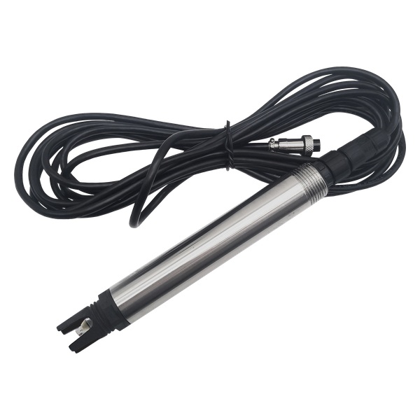
Verify the millivolt signal through the controller
Begin with a documented check solution suitable for the instruments. Use its assigned value for the relevant reference system and test temperature, following the manufacturer's procedure. Record lot identity, temperature, condition, stabilization and readings before any adjustment. If the solution certificate lists several reference electrodes, select the value corresponding to the delivered reference; document any existing offset at the transmitter or PLC so a reference correction is not applied twice. A successful solution check demonstrates response under that condition. It does not characterize the complete reaction mixture at the reactor or determine the process alarm threshold.
On the delivered digital version, compare signed register data and units with the local result. Confirm the negative as well as the positive part of the mapping through an appropriate documented simulation if both are used. On an analog version, verify transmitter and PLC span settings at multiple test points. Capture local measurement, PLC value and archived timestamp together. A sign error, incorrect full scale or held value can change the alarm even when the probe's electrochemical response is correct.
Place the output in the site's authorized commissioning mode before simulating a fault. Interrupt the instrument signal and record whether the operator sees a distinct invalid state. Restore the signal, observe the first fresh reading and check the event log. Verify that loss of communication cannot look like a valid low millivolt alarm or a steady reading. Preserve the old instrument ID and setpoint revision in the historian when the new channel enters service.
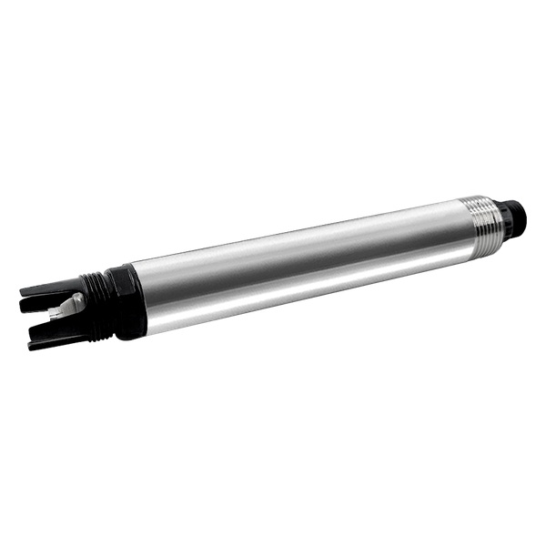
Specify the evidence needed to transfer the alarm
Give bidders the old model and configuration, reference basis if known, mounting arrangement, temperature and chemistry range, recorded normal and event traces, and the control action attached to the alarm. Identify the smallest decision difference the plant needs to distinguish and the time available for response. Request written information on reference construction, output variant, instrument accuracy and host configuration for the exact offered model.
Assign a party to supply the comparison equipment, witness paired runs, investigate discrepancies and approve the operating threshold. Include a contingency for a batch condition that cannot be observed during commissioning. A completed loop test closes the electrical item. The process owner still needs a record of how the new measurement supports decisions near the boundary where operators actually act.
Send the project data
For an application review, include paired traces, the old alarm logic, the intended reference check and the drawing of the measuring point. Identify the requested YEX-S1PRO-ORP output configuration and any reference details that still need written confirmation.
Send Your Project RequirementsFrequently asked questions
Q1. Can we copy the existing ORP setpoint into the new controller?
A1. Use the old value as a candidate for comparison. Identify what action it triggered and on which reference basis it was established. Compare the new channel with the old channel or an independently verified comparator in the actual water, then confirm that the proposed alarm gives the intended decision near the operating boundary.
Q2. Why do two probes in the same tank show different millivolts?
A2. Check their measuring surfaces, reference systems, condition, location and settling time. ORP reflects the mixed chemistry acting at the electrode surface. A reference difference, a coated surface or a different local water condition can all contribute. Compare the two instruments in an appropriate check solution and again side by side in the process.
Q3. Is a constant difference enough to justify an offset?
A3. A steady difference is a reason to investigate the reference convention and measurement chain. Repeat the comparison under several relevant operating conditions, including the alarm region. If the gap changes with chemistry or timing, one offset will not reproduce the historical decision. Document the process owner's acceptance criteria before entering any adjustment.
Q4. How should temperature be handled in a verification test?
A4. Record solution and process temperatures separately. Use the assigned check-solution value for the actual temperature and reference system under the manufacturer's procedure. Ask what the offered instrument's compensation setting changes. A correction used during verification cannot generally transform a mixed process-water reading into the value it would have at another temperature.
Q5. What if the old ORP probe has already failed?
A5. Use a separately verified instrument with a documented reference basis and obtain independent evidence for the process condition that drives the alarm. Archived trends help identify the operating region to investigate. They cannot establish a simultaneous comparison that was never made. Document how the provisional decision will be managed until representative conditions occur.
Q6. How can we distinguish a slow response from a shifted reading?
A6. Align the timestamps and examine both the transition and the eventual plateau during a documented process change. If the two channels eventually converge, inspect mounting, sample delivery, electrode condition and filtering. Compare the time to warning against the operator's response window before deciding that an electronic offset would address the discrepancy.
Q7. Which wiring or register faults can mimic an ORP problem?
A7. Check a known signed value from the instrument to the receiving system. Verify register representation and scaling for digital output, or configured current span for analog output. Then disconnect the signal under the approved commissioning procedure. The display should indicate loss of measurement and preserve the time of the last valid result.
Q8. What belongs in the replacement handover record?
A8. Keep old and new model identifiers, reference information, output settings, the comparison procedure, paired process readings and the independent outcome near the alarm. Record the effective date, approved threshold, alarm delay and responsible owner. Mark any untested operating conditions explicitly so a later shift knows when to seek a fresh confirmation.
Summary
Transfer an ORP alarm only after the reference basis, process comparison, response time and controller interpretation have been checked together. Keep the old and new records identifiable. Confirm the ordered YEX-S1PRO-ORP reference and output, then hand over the signed scaling test, paired traces near the decision point and the process owner’s approved response to an invalid signal.


