


 Chinese
 Spanish
 French
 Russian
 German
 Portuguese
 Indonesian
 Thai
 Vietnamese
 Arabic


Equalization tank pH monitoring becomes more demanding when several wastewater streams reach the same basin. A production drain may run steadily while cleaning wastewater arrives in short batches. Another branch may remain dry between transfers. Their temperature, suspended material and acid or alkaline character can differ, so one tank reading cannot describe every incoming stream.
The practical starting point is the water path: what reaches the tank, when it arrives, how it mixes and where water leaves. These conditions determine whether a mixed-tank measurement answers the operating question or whether a selected branch or outlet needs separate observation. Additional points should follow a real monitoring need, not the number of pipes on a drawing.
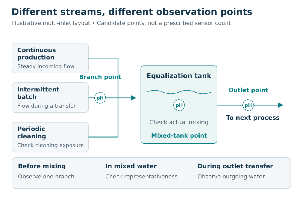
Illustrative multi-inlet layout: branch, mixed-tank and outlet points observe different water conditions.
Start with the Streams Entering the Tank
For each inlet, identify its wastewater source, discharge pattern and relevant operating conditions. Distinguish routine production water from cleaning discharges and unusual batches. Note whether the branch flows continuously, periodically or only during a transfer. A convenient sampling point may contain old standing water between events rather than the wastewater currently entering the tank.
Describe expected temperature, solids, oils or coating material, and known chemical exposure. Unknown composition remains a selection question; a pH range alone does not establish material compatibility. Cleaning exposure also matters if the installed probe encounters the cleaning stream.
These observations establish the measurement need. A mixed-tank point describes combined conditions at its location. A branch point observes that branch before commingling. An outlet point observes water moving toward the next process. Their readings serve different purposes even when the same type of pH sensor is used.
Match Equalization Tank pH Monitoring to the Flow Pattern
Continuous inflow and intermittent discharge create different installation demands. In a continuously wetted location, an immersion arrangement may provide regular contact with the process water. On an intermittent branch, confirm that the sensing end is exposed to the actual discharge, not air, stagnant liquid or a small residual pocket.
A short batch may be poorly represented by an occasional check outside its discharge period. Coordinate observations with the real operating sequence. Do not interpret a quiet trend during a dry or inactive period as evidence that the next batch will be similar.
If an inlet measurement is intended to support holding or investigating a batch, confirm that the information can reach the responsible operator while that action remains feasible. Extra instrumentation does not create a holding tank, isolation valve or treatment capacity. Where the objective is simply to observe mixed conditions, a separate branch point may add little useful information.
Account for Mixing, Bubbles and Deposits
A probe near an incoming jet may see a local stream before it has mixed with the basin. A probe in a sheltered corner may see water that exchanges slowly with the main flow. Neither location automatically represents the condition of the whole tank or its outlet.
Check the location under the mixing states that actually occur, including changes in mixer or pump operation. Keep the sensing end away from persistent air pockets, sediment burial and direct mechanical impact. A position beside an aerator may be accessible yet experience conditions that make a stable, representative measurement difficult.
The installation needs suitable contact with moving process water and practical access, rather than a universal distance from the wall or a fixed immersion depth. EPA guidance on equalization treats mixing as part of blending variable wastewater; adding sensors cannot compensate for an unsuitable hydraulic arrangement.
Check the Lowest Operating Level
A location that works when the tank is full may become exposed during drawdown. Compare the proposed sensing position with the lowest operating level, the outlet arrangement and the expected solids layer. Simply lowering the probe can exchange one problem for another if the sensing end becomes buried or enters a poorly mixed zone.
The holder must keep the sensor in its specified orientation and permit removal without unsafe access. Confirm the physical arrangement with the actual sensor dimensions and connection, not only a photograph of another installation.
Where a representative, maintainable immersed position cannot be achieved, the measuring arrangement needs further review. A separate flow-through arrangement is not an automatic substitute: sample supply, retention, exposure and service requirements must also be established. No arrangement should be assumed to remain valid when the sample stops flowing.
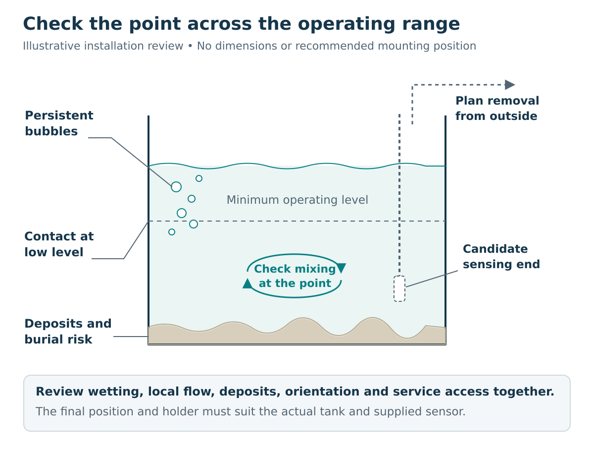
Illustrative installation review: check minimum water level, mixing, deposits and access together.
Add Locations Where the Combined Reading Is Not Enough
Use the following table to connect the multi-inlet conditions to the question each location can answer. It is a placement guide, not a prescribed number of instruments.
| Conditions at the tank | Monitoring need | Appropriate location to assess |
|---|---|---|
| Several streams mix sufficiently, and the required decision concerns the combined water | Follow the mixed condition through relevant operating states | A representative, serviceable mixed-tank point; separate branches may not be necessary |
| A selected branch carries distinct intermittent discharges that require individual attention | Observe that branch before it joins the other streams | A wetted branch location that captures the discharge, alongside the mixed-tank point |
| The outgoing stream is the concern and its condition is not adequately represented by the tank point | Observe water entering the next process | An outlet location exposed to the actual transfer flow |
| The objective is to compare incoming and outgoing behavior | Observe both boundaries during an agreed operating period | Combined-inlet and outlet locations, interpreted with flow and mixing conditions |
A combined-inlet point is already downstream of the branch junctions, so it does not provide the same source separation as individual branch points. Likewise, two sensors beside each other address measurement reliability at that position rather than coverage of different wastewater streams.
Do not average branch pH values to predict tank pH. pH is logarithmic and differs from acid-neutralizing capacity; the chemistry of the mixture matters. Nor does a branch reading alone prove which batch caused a later downstream change.
Make Cleaning and Verification Practical
Incoming solids, films and deposits can change the service needs of each location. A branch receiving coating material may need different attention from the mixed basin. Select a holder and access route that allow the sensing end to be inspected, cleaned and checked without unnecessary disturbance to operation.
Use the applicable sensor instructions and site procedures for cleaning. Do not prescribe one chemical or fixed cleaning interval for all wastewater. Record the condition before cleaning and the response afterward so that maintenance changes are not confused with changes in incoming water.
Before extending a layout because readings appear inconsistent, check the existing point. Compare readings under matching conditions using the agreed reference method, and examine wetting, deposits and signal presentation. Additional sensors are not a substitute for restoring confidence in an unreliable existing measurement.

YEX-S1-PH sensing end, shown for inspection and cleaning access planning.
Relate the Conditions to a Suitable pH Sensor
The YEX-S1-PH online pH sensor can be considered for a suitable digital pH point in this arrangement. Its documented features must be matched to the actual exposure and installation, not generalized to every industrial wastewater stream.
| Site condition to establish | Relevant S1-PH information and selection boundary |
|---|---|
| Normal, batch and cleaning temperature at the probe | Working temperature is 0–65°C; verify the actual exposure rather than the usual tank temperature alone |
| Pressure at the measuring arrangement | Working pressure is below 0.2 MPa; a pipeline arrangement needs its own pressure check |
| Wastewater and cleaning chemistry | POM is specified; confirm the complete assembly’s compatibility with the identified wastewater and cleaning exposure |
| Holder and signal connection | Immersion mounting with a 3/4 NPT thread and RS485 Modbus RTU output require a suitable mechanical arrangement and compatible receiver |
These details are documented in the S1-PH user manual. Confirm the supplied configuration and connection documents for the project. The sensor supplies measurement data; alarms, recording, remote transmission and control actions belong to the selected receiving system and its configuration.

YEX-S1-PH online pH sensor; suitability depends on the actual exposure and installation.
FAQ
1. Does equalization tank pH monitoring require a sensor on every inlet?
No. Separate inlet measurements are useful when individual streams need observation before mixing and the information supports a defined response. If the operating question concerns representative mixed water, one suitable tank point may be sufficient. Describe the branches and their discharge patterns before deciding which locations need permanent measurement.
2. Why can branch pH differ from the mixed-tank reading?
The branch and tank represent different water conditions. Mixing, other incoming streams and the timing of a discharge can change what each point observes. A difference does not by itself indicate a faulty probe. Check the actual flow path and operating state, and explain whether the project needs branch information or the combined condition.
3. What matters most on a branch that flows intermittently?
The sensing end must contact the relevant discharge when measurement is needed. Standing water between batches may not represent the next incoming stream, and a dry location cannot provide that process measurement. Establish the discharge sequence and mounting conditions, then request an arrangement that can be inspected and maintained under those conditions.
4. How should low tank level affect the installation?
The proposed point must remain suitable at the lowest operating level used for monitoring. Check wetting, orientation, nearby sediment and the flow around the sensing end. A deeper position is not necessarily better. Provide the level range and holder arrangement so that the installed position can be reviewed before equipment is selected.
5. Should a pH probe be placed close to an aerator or inlet?
Not simply because the location is convenient. Incoming jets, persistent bubbles and local unmixed water can make that position unsuitable for the intended reading. Review actual mixing and contact conditions while keeping service access practical. If the purpose is to observe an incoming branch, distinguish that deliberately from a point intended to represent mixed water.
6. When is an outlet point useful alongside the tank point?
It is useful when the project needs to observe the water transferred to the next process and the tank point does not adequately represent that stream. Confirm the outlet flow and transfer sequence before choosing the mounting arrangement. Retain any required existing point, and do not assume that outlet pH alone demonstrates complete treatment performance.
7. Can S1-PH be used with any wastewater entering the tank?
No. Suitability depends on the actual water and cleaning exposure, temperature, pressure, mounting and maintenance conditions. Its documented temperature range is 0–65°C and working pressure is below 0.2 MPa, but these limits do not establish chemical compatibility. Share the stream information and request a configuration review rather than selecting from pH range alone.
8. Can several S1-PH points connect directly to a monitoring platform?
They provide RS485 Modbus RTU measurement output, not independent cloud connectivity. A compatible controller, logger or gateway must receive the data and support the required onward connection. Confirm receiver capacity, addressing, cable arrangement and required functions for the selected system. Do not infer device count, transmission distance or alarm behavior from the interface name alone.

YEX-S1-PH connection detail; the receiving system handles recording, alarms and onward communication.
Summary
Multi-inlet equalization monitoring starts with the wastewater streams and the conditions around each measurement location. Intermittent flow, mixing, bubbles, low level, deposits and cleaning access determine whether a tank, branch or outlet point can provide useful information. Select the sensor after these requirements are clear. For a multi-point pH layout review, share the wastewater sources, discharge pattern, operating conditions, existing points and receiving-system details with YexSensor.


