


 Chinese
 Spanish
 French
 Russian
 German
 Portuguese
 Indonesian
 Thai
Thai Vietnamese
 Arabic

A purchase decision for turbidity sensor cleaning frequency starts with the required process action. Confirm the YEX-S1PRO-TS range, representative location, Modbus data path and acceptance method while accounting for fixed intervals that ignore real fouling conditions.
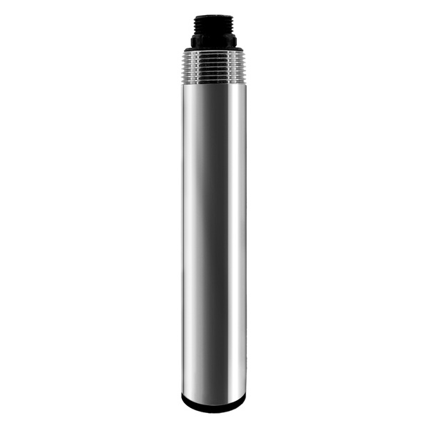
Lifecycle decision for Turbidity Sensor Cleaning Frequency
For surface water and wastewater stations, the specification must support the decision to derive cleaning frequency from inspection records and manage the risk of fixed intervals that ignore real fouling conditions; name the process event, required response, verification method, responsible owner and acceptance record for that decision instead of relying on a generic product statement.
What Turbidity Sensor Cleaning Frequency Must Deliver for Project Buyers
The search is driven by unreliable data, excessive field visits or uncertainty about whether cleaning, calibration or replacement is justified; for surface water and wastewater stations, the YEX-S1PRO-TS measurement deliverable is a maintainable point that supports the decision to derive cleaning frequency from inspection records; evaluate its sensor, mounting, power, communications, alarm handling and reference procedure together before the project can derive cleaning frequency from inspection records.
Interest in river water quality is relevant only when the project converts the phrase into a defined location, engineering unit, alarm purpose and verification plan for surface water and wastewater stations.
Where YEX-S1PRO-TS Fits in the Monitoring System
The online turbidity sensor sits between the process and the controls layer. YEX-S1PRO-TS provides the verified measurement and RS485 data; brackets, sample conditioning, panel power, surge protection, gateway, HMI tags and maintenance records complete the measurement point. In surface water and wastewater stations, this architecture must preserve the context needed to derive cleaning frequency from inspection records.
For surface water and wastewater stations, choose the location from the decision to derive cleaning frequency from inspection records; an upstream point supports warning, a mixed process point supports control, and a final point supports verification; one sensor location should not be assigned all three duties unless the hydraulics and response time make that defensible.
For YEX-S1PRO-TS, separate the probe from the balance of system in the bill of materials; identify the required mounting or flow cell, isolation, drain, waterproof junctions, controller or gateway, cabinet protection, commissioning, calibration materials and spares for surface water and wastewater stations; the quotation should assign supply and validation responsibility for every item.
Online Turbidity Sensor Communication and Protocol Compatibility
RS485 establishes the physical bus and Modbus RTU defines the message exchange, but neither guarantees correct engineering data; the controls submittal for YEX-S1PRO-TS should include serial settings, register definitions, scaling, units and the behavior expected during invalid data, timeout and restart; for surface water and wastewater stations, the register approval must support the stated decision to derive cleaning frequency from inspection records.
The historian for turbidity sensor cleaning frequency should preserve the raw engineering value together with quality and service states; configure timeout and stale-data rules separately from process alarms, and test the recovery sequence after power loss so an old value cannot silently re-enter control logic.
Verified Technical Parameters and Procurement Checks
| Selection item | Verified YexSensor specification | Project procurement check |
|---|---|---|
| Measurement ranges | 0–200 / 1,000 / 4,000 NTU; customizable | Choose from actual clean, normal and upset samples. |
| Resolution and accuracy | 0.1 NTU; ±3%; temperature ±0.1°C | Set acceptance against the ordered range and site reference. |
| Response time | 10 s | Configure filtering without hiding short carryover events. |
| Power and consumption | 12–24 VDC; 0.4 W | Check power budget and grounding. |
| Output | RS485 Modbus RTU; optional 4–20 mA | Approve register map, scaling and fault values. |
| Housing and cable | 316L + ABS; 5 m four-core shielded cable | Confirm water chemistry and cable distance. |
| Operating limits | 0–50°C, non-freezing; pressure <0.2 MPa; IP68 | Keep the window over 10 cm from the bottom and over 3 cm from walls. |
| Cleaning and mounting | Optional self-cleaning; immersion, 3/4 NPT | Specify cleaning where biofilm or solids deposition is credible. |
The table uses the current YexSensor manual or official product page for YEX-S1PRO-TS; do not transfer these values to another model, product generation or customized option; for surface water and wastewater stations, the quotation should repeat the selected range, output, cable, material information where published, mounting and accessories, and it should account for fixed intervals that ignore real fouling conditions so engineering can verify the supplied configuration.
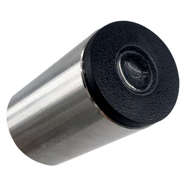
Engineering Scenarios for Online Turbidity Sensor
1. Inspect before adjusting in surface water and wastewater stations
Field challenge: fouling, bubbles, position change and cable damage can resemble calibration drift; the design must also account for fixed intervals that ignore real fouling conditions. System integration: record visual condition and as-found reading before cleaning or changing calibration data; configure YEX-S1PRO-TS within its verified limits and keep the measurement purpose tied to the decision to derive cleaning frequency from inspection records. Project value for surface water and wastewater stations: the service record identifies the actual cause instead of hiding it with an offset.
2. Verify with a suitable reference in surface water and wastewater stations
Field challenge: old standards, poor stabilization or nonrepresentative samples can create false failures; the design must also account for fixed intervals that ignore real fouling conditions. System integration: use the parameter-specific procedure, record temperature and timing, and compare across more than one relevant point when required; configure YEX-S1PRO-TS within its verified limits and keep the measurement purpose tied to the decision to derive cleaning frequency from inspection records. Project value for surface water and wastewater stations: maintenance decisions are based on traceable evidence.
3. Restore the data path in surface water and wastewater stations
Field challenge: a serviced probe may return with the wrong address, range, scaling or alarm state; the design must also account for fixed intervals that ignore real fouling conditions. System integration: confirm mechanical condition, raw registers, HMI units, maintenance flag and alarm recovery before releasing the point; configure YEX-S1PRO-TS within its verified limits and keep the measurement purpose tied to the decision to derive cleaning frequency from inspection records. Project value for surface water and wastewater stations: operations receives a complete measurement channel rather than only a cleaned probe.
4. Plan spares and service intervals in surface water and wastewater stations
Field challenge: fixed calendars can either waste labor or allow long periods of degraded data; the design must also account for fixed intervals that ignore real fouling conditions. System integration: adjust intervals from fouling history, criticality and travel time, and hold model-specific consumables plus configuration records; configure YEX-S1PRO-TS within its verified limits and keep the measurement purpose tied to the decision to derive cleaning frequency from inspection records. Project value for surface water and wastewater stations: multi-site teams reduce downtime without claiming the sensor is maintenance-free.
How to Select YEX-S1PRO-TS for Surface Water and Wastewater Stations
Begin model selection with actual data from surface water and wastewater stations: minimum, typical, warning and credible upset conditions; for YEX-S1PRO-TS, the first published selection item is measurement ranges (0–200 / 1,000 / 4,000 NTU; customizable); procurement action: Choose from actual clean, normal and upset samples; if site records omit seasonal, cleaning or batch events, agree on a sampling campaign or trial for surface water and wastewater stations.
Review the complete water matrix, not only the target parameter; temperature, pressure, pH, conductivity, solids, color, bubbles, oil, oxidants, reducing chemicals and biological growth can affect the surface water and wastewater stations service interval or representativeness; bubbles, wall reflections, settled solids and window coating must be controlled by sample-point design and maintenance; obtain written confirmation whenever conditions related to fixed intervals that ignore real fouling conditions fall outside routine service.
Choose immersion for YEX-S1PRO-TS when the point in surface water and wastewater stations stays wetted, mixed and safely accessible. Use a bypass for surface water and wastewater stations when pressure, temperature, access or sample conditioning must be controlled. Define flow, isolation, drainage and transport time because the stated IP rating cannot correct unsuitable surface water and wastewater stations hydraulics.
System Integration and Installation Notes
Treat hydraulics as part of instrument accuracy for surface water and wastewater stations; document flow direction, mixing, bubbles, solids deposition and sample delay for this duty; provide isolation and drainage where a side stream is used, and make removal possible without pulling on the cable or exposing personnel to an uncontrolled process.
At the panel, document polarity, protective devices, terminals, shield treatment and cable segregation; in software, record the approved YEX-S1PRO-TS register revision, address, baud rate, scaling and units; a replacement should be configurable from the handover file without reverse engineering; for surface water and wastewater stations, confirm that this controls design supports the decision to derive cleaning frequency from inspection records.
RFQ Checklist and Inquiry Information
Distributors should attach end-user conditions rather than forwarding only a parameter name; for surface water and wastewater stations, include ranges, water analysis, temperature, pressure, flow, nearby dosing, mounting sketch, RS485 settings, cable length, quantity, destination, acceptance method and required support; the request applies to surface water and wastewater stations and must support the decision to derive cleaning frequency from inspection records.
Require the offer to identify YEX-S1PRO-TS, ordered range, accuracy, output, protocol document, wetted construction, cable, connector, mounting, cleaning provision, controller or gateway, calibration materials, spares, warranty, lead time and exclusions; price optional items separately so competing bids describe the same installed duty; apply the comparison to the stated surface water and wastewater stations duty.
Send a Project-Ready Inquiry
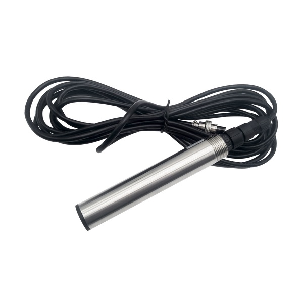
For surface water and wastewater stations, attach the water matrix, operating ranges, installation sketch, cable distance, PLC or gateway details, quantity and acceptance method. State how the project will derive cleaning frequency from inspection records. Review the YEX-S1PRO-TS online turbidity sensor for turbidity sensor cleaning frequency, then Send Your Project Requirements for configuration review.
Frequently Asked Questions About Turbidity Sensor Cleaning Frequency
How does YEX-S1PRO-TS integrate with PLC, SCADA or an IoT gateway for turbidity sensor cleaning frequency?
For turbidity sensor cleaning frequency, YEX-S1PRO-TS provides RS485 Modbus RTU as listed in the verified table; approve the surface water and wastewater stations protocol revision, device address, baud rate, parity, registers, data type, byte order, scaling and units; during commissioning, compare each used tag with the stabilized field value and test timeout, stale-data indication and power-cycle recovery before any automatic action is enabled.
How should YEX-S1PRO-TS accuracy be verified for projects involving surface water and wastewater stations?
For this online turbidity sensor, catalog accuracy is not the complete site-acceptance tolerance because installation, matrix, timing, stabilization and the reference method add uncertainty; collect paired surface water and wastewater stations results at the same point and time across typical and warning conditions, recording temperature and maintenance state; where the project is exposed to fixed intervals that ignore real fouling conditions, expand the trial before accepting the value for control or contractual reporting.
Which data-quality fields should YEX-S1PRO-TS send in surface water and wastewater stations?
Store the online turbidity sensor value, unit, configured range, timestamp, communication status, maintenance flag and last-valid time; retain temperature when YEX-S1PRO-TS provides it and record configuration changes in the historian; for surface water and wastewater stations, alarms must separate a process excursion from cleaning, dry exposure, invalid data or bus loss; a plausible held value is not proof of a stable process.
Which YEX-S1PRO-TS measuring range fits the measurement point in surface water and wastewater stations?
Use minimum, typical, warning and credible maximum values from the actual surface water and wastewater stations point, including seasonal, batch, cleaning and startup conditions; select a verified YEX-S1PRO-TS range that covers the duty while retaining useful operating-band resolution; for surface water and wastewater stations, do not copy another model's range or assume customization; require a sampling campaign or field trial when records are incomplete.
Should YEX-S1PRO-TS use direct immersion or a bypass in surface water and wastewater stations?
Use direct immersion for the online turbidity sensor when the surface water and wastewater stations location remains wetted, mixed and safely accessible with a protected cable route; in surface water and wastewater stations, select a bypass when pressure, heat, access or conditioning requires controlled sample flow; define representative takeoff, isolation, drainage and delay, then compare both arrangements against response time, bubbles, deposits and reference-sampling access before ordering YEX-S1PRO-TS.
Which site conditions in surface water and wastewater stations can make YEX-S1PRO-TS data unrepresentative?
For this online turbidity sensor, stagnant water, walls, sediment, aeration bubbles, direct dosing, incomplete mixing, changing depth or sample-line delay can separate a valid reading from the intended decision; the specific surface water and wastewater stations concern is fixed intervals that ignore real fouling conditions; survey the surface water and wastewater stations hydraulics and compare simultaneous reference samples before fixing alarms; repeat the review after a process or mounting change.
What project data should an RFQ for turbidity sensor cleaning frequency include?
The RFQ should provide the surface water and wastewater stations flow, measurement objective, water matrix, four-point range data, temperature, pressure, level or flow, mounting drawing, cable distance, power, PLC or gateway, quantity, destination and commissioning date. State the decision to derive cleaning frequency from inspection records and the acceptance reference so YexSensor can quote the sensor, mounting, controls, cleaning provisions, calibration materials and spares as one project scope.
How should distributors compare quotations for projects involving surface water and wastewater stations?
Normalize every offer to the same surface water and wastewater stations duty. Compare the surface water and wastewater stations measurand, model, range, accuracy, output, protocol revision, wetted materials, cable, bracket or flow cell, conditioning, controller, documents, commissioning, spares, warranty, lead time and exclusions. Resolve surface water and wastewater stations deviations in writing because a lower probe price may omit hardware or support required for an accessible, acceptable point.
What should FAT and SAT cover for YEX-S1PRO-TS on projects involving surface water and wastewater stations?
For YEX-S1PRO-TS, FAT should verify nameplate, ordered range, output, cable, accessories, documents, registers and basic fault simulation; SAT should add surface water and wastewater stations installation inspection, reference comparisons, quality states, alarm delay and hysteresis, communication loss and power recovery; close handover only after the complete signal path supports the project decision to derive cleaning frequency from inspection records; one plausible live value is insufficient.
Summary
The selection boundary for the YEX-S1PRO-TS measurement point is clear: verified product data does not replace representative hydraulics, matrix review or an agreed reference method. In surface water and wastewater stations, YEX-S1PRO-TS should be purchased only after the project shows how it will derive cleaning frequency from inspection records and manage the effects of fixed intervals that ignore real fouling conditions.
Complete the surface water and wastewater stations design with suitable mounting, DC power, an approved Modbus data contract, stale-data logic, cleaning, spares and an acceptance test; for a useful YexSensor quotation, submit the matrix, operating ranges, temperature, pressure, flow or level, drawing, cable distance, PLC or gateway details, quantity, destination, reference method and schedule; these inputs let buyers compare a maintainable measurement scope for a project that can derive cleaning frequency from inspection records, rather than an ambiguous probe price.



