


 Chinese
 Spanish
 French
 Russian
 German
 Portuguese
 Indonesian
 Thai
Thai Vietnamese
 Arabic

online turbidity sensor selection should be engineered as a measurement and data system, not purchased as an isolated device. Select a turbidity sensor from the actual water matrix, normal and upset NTU values, optical fouling rate, mounting hydraulics and required output. A wider range is not automatically a better purchase: it can sacrifice the fit between normal operation, resolution, alarm purpose and maintenance access.
Integrators are trying to avoid range saturation during an event, poor sensitivity in normal water, bubble interference, a coated optical window and mismatched analog or Modbus configuration. Buyers also need to know whether turbidity is being used as a process indicator or as a formal reporting measurement requiring a specified reference method.
Project Background and Buyer Risk
A buyer researching online turbidity sensor selection is normally planning a station, correcting unreliable field data or preparing a commercial comparison. The product must fit the site, connect to the specified system and remain serviceable. Link every measurement to an operating, reporting or maintenance action in the first design document.
Assign ownership for the online turbidity sensor selection data and field asset. The distributor may supply hardware, the integrator may program the controller, a civil or marine contractor may install the structure, and the owner may operate the platform. Show every inclusion, exclusion and deliverable in the quotation to prevent unassigned commissioning work.
Where the Product Sits in the Monitoring System
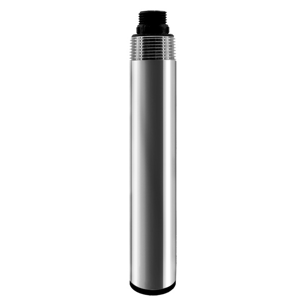
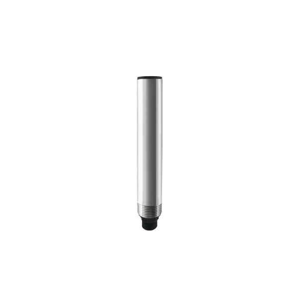
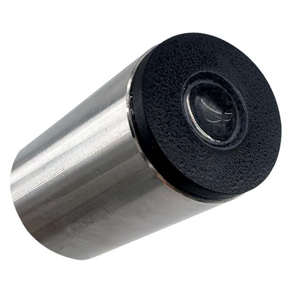
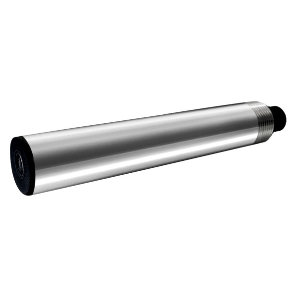
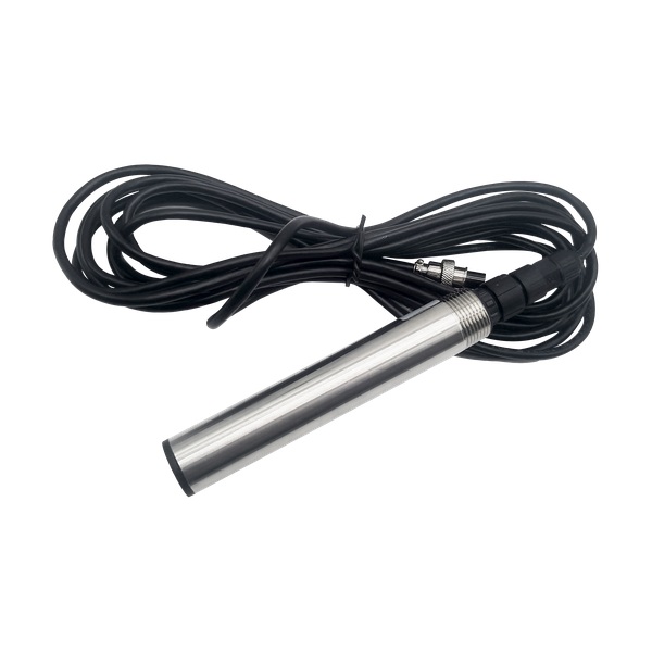
The YexSensor S1Pro turbidity sensor uses infrared optical scattering and can be immersed through an NPT 3/4 connection. Its digital value can be polled by a PLC, RTU or gateway when RS485 Modbus RTU is ordered. The optional 4–20 mA version is an alternative output; the RFQ must select one.
In a online turbidity sensor selection project, the integrator must follow the whole signal path: sensing, local power, cable and connectors, controller configuration, communication health, data storage, engineering-unit conversion, alarms and operator response. A fault state must be distinguishable from a valid stable value. Preserve the raw value, status, timestamp and configuration revision for post-handover review.
online turbidity sensor selection: Communication and Industrial Compatibility
For online turbidity sensor selection, RS485 Modbus RTU lets a PLC, RTU, data logger or IoT gateway poll field devices over a defined serial bus. Compatibility is not automatic. Confirm supply voltage at the load, shield and grounding practice, topology, termination, unique slave address, baud rate, parity, function code, register address, data type, byte order, scale and engineering unit.
Bench commissioning of the online turbidity sensor selection package should use the exact ordered hardware. Read every required register, interrupt power, break the communication link and verify recovery. The supervisory platform should mark stale data and communication loss rather than display the last normal-looking number. Coordinate surge protection and grounding for every long outdoor route.
Verified Technical Parameters and Procurement Meaning
The online turbidity sensor selection values below come from the relevant YexSensor product information reviewed for this application. Confirm the exact model revision in the quotation. If the project requires an unlisted parameter, request written confirmation instead of assuming an industry-typical value.
| Project item | Verified value or option | Procurement check |
|---|---|---|
| Measurement principle | Infrared LED optical scattering | Review bubbles, color, deposits and particle properties at the site |
| Ranges | 0–200, 0–1000 or 0–4000 NTU; customization available | Select against normal and upset values, not only the maximum |
| Resolution / accuracy | 0.1 NTU / ±3% | Define the acceptance comparison and sample condition |
| Response time | 10 s | Coordinate polling, filtering and alarm delay |
| Supply / power | 12–24 V DC / 0.4 W | Include cable voltage drop and cabinet protection |
| Output | RS485 Modbus RTU; optional 4–20 mA, select one | State the required output in the RFQ |
| Construction / rating | 316L + ABS / IP68 | Confirm chemical compatibility and the sealing of the complete installation |
| Cable / mounting | 5 m four-core shielded cable / NPT 3/4 immersion | Cable jacket material is not stated; confirm it with length, bracket, depth and service clearance |
| Environment | 0–50 °C, nonfreezing; pressure below 0.2 MPa | Do not place it in an unsupported pressurized or freezing duty |
| Cleaning | Optional self-cleaning configuration | Select it where fouling rate justifies the added mechanism |
Solution and Installation Options
The online turbidity sensor selection method should follow the site decision and maintenance reality. Use this comparison as a design screen, then validate the selection with drawings, water data and an agreed acceptance method.
| Option | Suitable project condition | Engineering question before purchase |
|---|---|---|
| 0–200 NTU range | Cleaner water and smaller process deviations | Confirm normal value, required alarm sensitivity and reference comparison |
| 0–1000 NTU range | General surface water and wastewater applications | Check event peaks and routine window cleaning |
| 0–4000 NTU range | Higher-solids duty within the verified sensor application | Confirm that optical measurement remains suitable and accessible |
| Custom range inquiry | Projects outside the listed configurations | Provide representative samples or historical data and obtain written confirmation |
Systematic Industry Application Scenarios
1. Filter outlet monitoring
Field environment challenge: Normal turbidity may be low, but a breakthrough event needs rapid recognition
System integration solution: Select the lower suitable range, install without bubbles and send a persistent alarm to the PLC.
User value: Operators can investigate filter performance using trends tied to backwash and process state.
2. Wastewater outlet
Field environment challenge: Solids, color and fouling change during loading and cleaning
System integration solution: Use a representative flowing point, select range from normal and upset data, and plan optical-window cleaning.
User value: The plant gains a continuous process warning while retaining the required compliance sampling method.
3. River station
Field environment challenge: Runoff can create short high-NTU events and deposits on fixed sensors
System integration solution: Protect the probe from debris, maintain immersion, log rainfall context and consider self-cleaning.
User value: The station captures event timing while maintenance records explain drift or fouling.
4. Aquaculture system
Field environment challenge: Feed, algae, bubbles and fish movement can create local variability
System integration solution: Choose a calm representative point and link turbidity trend to filtration or husbandry inspection.
User value: Farm staff can distinguish sustained solids change from brief handling disturbance.
5. Industrial reuse loop
Field environment challenge: Turbidity can indicate membrane, clarification or contamination problems
System integration solution: Install at a decision point with isolation for service and map values to equipment state in SCADA.
User value: Engineers can investigate process deviations before downstream equipment is exposed.
Selection Guide for Integrators and Project Buyers
1. Use historical minimum, typical, high and upset NTU data
Use historical minimum, typical, high and upset NTU data. If no data exist, plan a survey rather than selecting only from a catalogue maximum. For this online turbidity sensor selection requirement, the quotation should identify who verifies the condition, what evidence is supplied and whether a site-dependent accessory is excluded.
2. Specify water color, particle type, bubbles, oil, algae and fouling
Specify water color, particle type, bubbles, oil, algae and fouling. Optical scattering response can differ between matrices even at the same reported NTU. For this online turbidity sensor selection requirement, the quotation should identify who verifies the condition, what evidence is supplied and whether a site-dependent accessory is excluded.
3. Choose RS485 Modbus or optional 4–20 mA at quotation
Choose RS485 Modbus or optional 4–20 mA at quotation. Confirm the exact output, cable and controller input before shipment. For this online turbidity sensor selection requirement, the quotation should identify who verifies the condition, what evidence is supplied and whether a site-dependent accessory is excluded.
4. Keep the optical window submerged in representative moving water without direct bubbles, wall contact or sediment burial
Keep the optical window submerged in representative moving water without direct bubbles, wall contact or sediment burial. For this online turbidity sensor selection requirement, the quotation should identify who verifies the condition, what evidence is supplied and whether a site-dependent accessory is excluded.
5. Define how the online reading will be compared with a reference and what difference is acceptable for the process purpose
Define how the online reading will be compared with a reference and what difference is acceptable for the process purpose. For this online turbidity sensor selection requirement, the quotation should identify who verifies the condition, what evidence is supplied and whether a site-dependent accessory is excluded.
Compare the complete online turbidity sensor selection loop, not only the sensor unit price: mounting, cable, enclosure, power conditioning, controller, gateway, platform, field installation, configuration, reference checks, training, service parts and warranty boundary. That scope reveals commissioning cost before purchase.
System Integration, Commissioning and Lifecycle Controls
Commission the online turbidity sensor selection system against an approved I/O list and control narrative. Name the sensor, model, serial number, Modbus address, register, unit, normal range, alarm limits, update interval and fault behavior. State what the operator does after a warning and which decisions require a reference sample or manual confirmation.
Before evaluating online turbidity sensor selection data, inspect the mechanical installation. Verify sensor orientation and depth, bracket or buoy movement, cable strain relief, connector seals, enclosure condensation control and safe retrieval. Check polarity, voltage at the powered device, shield termination and surge protection. Keep photographs and the final drawing with the configuration backup.
Acceptance of online turbidity sensor selection needs more than one plausible displayed value. Observe a trend through a real change or controlled check, compare with the agreed reference under matched conditions, test alarms, label maintenance data, and verify local storage plus recovery after loss of power and communications. Record deviations and site limitations explicitly.
Review the first month of online turbidity sensor selection field data with operations staff. Adjust alarm persistence, visit intervals and cleaning only from documented behavior. Retain comparison checks, cleaning, part replacement, firmware or register changes and abnormal-event notes so distributors and integrators can support the installed system with evidence.
Project Information for a Comparable Quotation
For a online turbidity sensor selection quotation, send the operating conditions, not only a requested quantity. A useful RFQ should include:
- site type, water matrix, expected minimum/normal/maximum values and the decision supported by each measurement;
- installation drawing, depth or mounting geometry, cable route, ambient conditions and service access;
- power source, controller or gateway model, communication settings, data interval, alarms and platform boundary;
- required sensor output, accessories, spares, documentation, commissioning, training and acceptance method.
Review the relevant YexSensor product configuration, then Send Your Project Requirements with the site data needed to confirm the online turbidity sensor selection model and delivery scope.
FAQ About online turbidity sensor selection
How does an optical turbidity sensor measure NTU?
For this online turbidity sensor selection project, the S1Pro uses an infrared LED optical scattering principle. Suspended particles scatter the emitted light and the receiver converts the response into turbidity. Particle properties, bubbles, color and deposits can affect field behavior, so validate the sensor in the actual matrix.
Can turbidity be converted directly to suspended solids concentration?
For this online turbidity sensor selection project, not with one universal factor. The relationship depends on particle size, shape, color and density. Build a site-specific correlation from paired laboratory TSS and stable turbidity samples if the project wants an estimated solids trend, and keep the units distinct.
What happens when the optical window is coated?
For this online turbidity sensor selection project, deposits can bias or weaken the optical signal while the value may still look plausible. Use inspection, trend diagnostics and cleaning records; select the self-cleaning option where fouling justifies it, but still provide periodic manual verification.
Which NTU range should be ordered?
For this online turbidity sensor selection project, choose the narrowest verified range that covers normal variation and credible upset events with margin. YexSensor lists 0–200, 0–1000 and 0–4000 NTU configurations, with customization available. Submit historical data and the alarm purpose with the RFQ.
Should I order RS485 or 4–20 mA?
For this online turbidity sensor selection project, choose RS485 Modbus RTU for multi-drop digital integration and diagnostic-friendly data mapping. Choose 4–20 mA when the existing PLC only has analog inputs or the project standard requires it. The listed option is select-one, so state it explicitly.
When is self-cleaning worth specifying?
For this online turbidity sensor selection project, specify it when algae, biofilm, mineral scale or solids deposit faster than the planned manual visit interval and when the mechanism suits the installation. It reduces cleaning burden but does not eliminate inspection, reference comparison or replacement planning.
What should be included in a turbidity sensor RFQ?
For this online turbidity sensor selection project, provide normal and maximum NTU, water matrix, temperature, pressure, mounting, cable length, output choice, controller, polling interval, cleaning access, reference method and required accessories. State whether bracket, flow cell, gateway and commissioning are included.
How should the turbidity loop be accepted?
For this online turbidity sensor selection project, confirm model and range, inspect mounting, test the Modbus or analog scaling, observe response in the actual water, compare with the agreed reference under matched conditions, test alarms and document the clean baseline.
Can the sensor be installed in a pressurized pipe?
For this online turbidity sensor selection project, only within a correctly engineered fitting and the verified pressure limit. The S1Pro table states pressure below 0.2 MPa. Confirm process pressure, transients, isolation and service removal; use a flow cell or bypass if direct insertion is unsuitable.
Summary
Online Turbidity Sensor Selection is a procurement decision about Range, Fouling and Modbus Integration measurement fit, representative installation, verified communication and maintainable field operation. The YexSensor configuration described here can support the project when its published range, construction and interface match the real water and installation. It should not be stretched beyond documented limits or used as a substitute for required laboratory or civil-engineering work.
The decision boundary for online turbidity sensor selection is clear: select the sensing principle and range from real field conditions, place it where the value represents the intended action, and prove the complete data chain. A controller display is not acceptance by itself. Mounting or deployment, power quality, Modbus mapping, stale-data handling, reference comparison, maintenance access and ownership must be agreed before the station is handed over.
Before requesting a online turbidity sensor selection price, send expected values, water and site conditions, mounting or deployment drawing, cable and power details, PLC/RTU/gateway requirements, data interval, alarm purpose, maintenance access and acceptance method. Ask for explicit confirmation of model, output, accessories, documentation and responsibility boundaries. Those inputs allow a distributor or integrator to quote a working measurement loop rather than an incomplete sensor package.



