


 Chinese
 Spanish
 French
 Russian
 German
 Portuguese
 Indonesian
 Thai
Thai Vietnamese
 Arabic

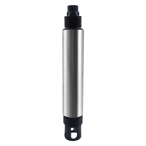
An online residual chlorine sensor should measure the disinfectant variable that the process actually controls and remain stable under defined pH, temperature and flow conditions. YexSensor YEX-S1Pro-FCL lists hypochlorous acid, residual chlorine, pH and temperature outputs, a 0–5.00 mg/L chlorine range, constant-voltage measurement with compensation, a 10-second response and RS485 Modbus RTU or optional 4–20 mA.
Why Buyers Search for a online residual chlorine sensor
Drinking-water plants, distribution stations, pools and disinfection skids search for continuous chlorine data because grab samples cannot show every dosing change or loss of residual. Their concerns include chlorine species, pH effects, sample flow, electrode condition, pressure, calibration and whether the controller will receive the correct digital or analog value. A procurement-ready scope must define the disinfectant and measurement point.
The first engineering task is to define the process event, available response time, acceptable uncertainty and action supported by the value. Trend, alarm, automatic control and regulatory reporting have different validation requirements. This decision determines the range, location, maintenance plan and reference method.
YexSensor YEX-S1Pro-FCL Product Positioning
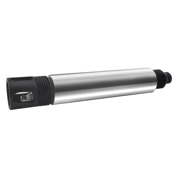
YEX-S1Pro-FCL lists residual chlorine from 0–5.00 mg/L with customization, pH from 0–14, residual-chlorine accuracy of ±5% of reading, pH ±0.1, temperature ±0.1°C and a 10-second response. It uses the constant-voltage method with pH and temperature compensation. The housing is 316L stainless steel plus ABS, rated IP68, and the operating environment is 0–50°C, non-freezing, below 0.2 MPa.
Published specifications are configuration boundaries, not proof that an unknown matrix or installation is suitable. Ask YexSensor to confirm the ordered range, output, wetted materials, cable and application limits on the quotation or attached datasheet.
Technical Parameters and Procurement Checks
| Technical item | Official product specification | Procurement check |
|---|---|---|
| Measured parameters | Hypochlorous acid, residual chlorine, pH and temperature | Define the chlorine species and PLC tags required |
| Residual chlorine range | 0–5.00 mg/L; customizable | Provide target, alarm and maximum dosing values |
| pH range | 0–14 | State actual process pH and compensation requirements |
| Accuracy | Chlorine ±5% of reading; pH ±0.1; temperature ±0.1°C | Compare absolute error with low residual limits |
| Response time | 10 seconds | Add sample transport and mixing delay |
| Measurement principle | Constant-voltage method with pH and temperature compensation | Confirm disinfectant chemistry suits this method |
| Outputs | RS485 Modbus RTU or optional 4–20 mA; select one | Specify register map or analog variable and scaling |
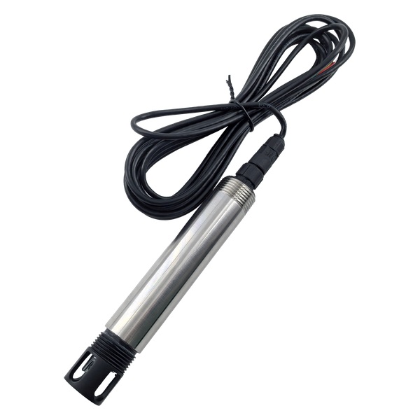
| Power and cable | 12–24 VDC, about 0.4 W; standard 5 m shielded cable | Confirm cable length and cabinet power |
| Construction and limits | 316L stainless steel plus ABS; IP68; 0–50°C; pressure below 0.2 MPa | Design flow or bypass conditions within limits |
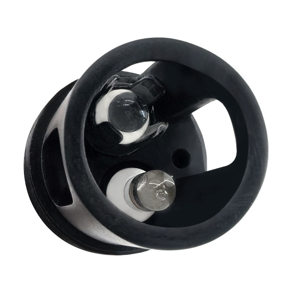
| Installation and maintenance | 3/4 NPT immersion arrangement | Define stable flow, electrode cleaning and reference sampling |
What the Specifications Mean in a Real Project
Residual chlorine is affected by disinfectant chemistry and pH. The RFQ should name the required chlorine species rather than asking for a generic chlorine value.
A 0–5.00 mg/L range covers many water-disinfection duties, but suitability depends on the target, low alarm and absolute error near the decision point.
The sensor response is 10 seconds, yet sample transport and tank or pipe mixing may dominate total control delay. Fast polling cannot remove hydraulic lag.
Stable flow and a representative location matter for constant-voltage measurement. A stagnant pocket or chemical injection plume can mislead automatic dosing.
pH and temperature outputs provide compensation context, but they do not replace verification of chlorine by the project reference method.
Separate the probe from the complete measurement point. Brackets, flow cells or bypasses, isolation, drain, power, surge protection, waterproof junctions, controller, gateway, calibration materials and spares can determine whether the delivered system is usable.
Acceptance and Lifecycle Planning
Write the site acceptance test before issuing the order. Define the reference method, comparison range, stabilization period, allowable difference and response when results fail. Include alarm, invalid-data, power-loss and communication-loss tests. If the value starts a pump, valve, diversion or dose, simulate that sequence in a safe test state.
Record range, engineering units, calibration status, cleaning events and protocol version with the time series. Assign who reviews drift, changes setpoints and releases a sensor after maintenance. Hold suitable cleaning tools, standards and critical spares. These details help buyers compare maintainable systems rather than probes with different hidden support needs.
Review sunlight, condensation, electrical noise, vibration, access and cable strain. Confirm retrieval, isolation and drainage so one technician can safely clean or verify the sensor. Where an alarm protects an important process, define a temporary reference check or fallback during maintenance.
Data Quality and Alarm Design
Store the raw value, engineering unit, configured range, quality flag and maintenance state together. A number without context can look valid after a cable fault, dry exposure or range change. Keep enough time resolution to investigate short events, but use persistence or rate-of-change logic where bubbles, cleaning cycles or batch transitions create harmless spikes.
Define warning, action, out-of-range, maintenance and communication-loss states separately. Every automatic response should have a reset condition, maximum operating time and manual override. The controller should reject impossible values and hold a documented safe state when communication is lost instead of treating zero as a genuine water result.
During handover, give operators a short diagnostic sequence: check the process, verify immersion and flow, inspect the measuring surface, compare a reference result, and then review wiring and communication. Record every cleaning, calibration and configuration change. This evidence distinguishes normal process variability from drift and prevents unnecessary recalibration that can make long-term trends harder to interpret.
Recommended Applications
Drinking-water treatment
Monitor post-contact residual at a representative point with reference checks.
Distribution monitoring
Trend residual loss with controlled sample flow and remote communication alarms.
Pool and process disinfection
Use chlorine, pH and temperature together where the disinfectant chemistry is confirmed.
Disinfection skid integration
Connect Modbus values to a PLC with dosing limits, invalid-data checks and manual override.
Mark every point on the process diagram with stream name, depth or sample flow, nearby dosing and return lines, expected range and operating action. A convenient but unrepresentative location can provide less value than a simpler sensor at the correct point.
online residual chlorine sensor: Selection Recommendations
Send disinfectant type, required chlorine species, target and maximum, pH, temperature, pressure, sample flow, water chemistry, measurement location, dosing point, pipe or bypass drawing, cable, output, controller and reference method. Ask the quotation to state the configured range and RS485 or 4–20 mA version explicitly.
A suitable configuration stays inside official limits, represents the process and remains safely serviceable. An unsuitable point exposes the sensor to unreviewed chemistry or pressure, confuses one parameter with another, or reports after the available response time has passed.
Installation, Integration and Maintenance
Choose a representative point after adequate mixing and contact time, not directly in a concentrated chemical plume. Maintain stable water contact, pressure below 0.2 MPa and non-freezing temperature within 0–50°C. Provide isolation, drain, reference sampling and safe electrode access. Test loss-of-signal and implausible-value handling before automatic dosing.
For RS485 Modbus RTU, confirm supply polarity, A/B convention, device address, baud rate, parity, stop bits and register map. Use appropriate topology, shielding and termination. Store final settings and PLC tag definitions with commissioning records.
Commissioning should include mechanical inspection, stable-value confirmation, reference comparison, alarm simulation and communication-loss testing. Values collected during cleaning, dry exposure or maintenance should be marked invalid rather than stored as process events.
How to Request a Comparable Quotation
Send the process diagram, water sources, measurands, units, minimum, normal and maximum values, temperature, pressure, pH, matrix components, mounting, cable, output, controller, power, quantity and destination. Add required drawings, certificates, packing and delivery terms.
Ask for line-item pricing for the sensor, mounting, cleaning option, controller, gateway, calibration materials, spares and commissioning. Compare cleaning labor, consumables, standards, replacement parts and field visits over the service period instead of comparing probe price alone.
Frequently Asked Questions About a online residual chlorine sensor
What chlorine range does YEX-S1Pro-FCL provide?
The published residual-chlorine range is 0–5.00 mg/L with customization available. Provide target, alarm and maximum values before selecting.
Does pH affect residual chlorine measurement?
Yes. Chlorine species and sensor response depend on chemistry. YEX-S1Pro-FCL includes pH and temperature compensation, but the disinfectant and operating matrix still require confirmation.
Can the sensor control a dosing pump directly?
Use it through a controller with persistence, dosing limits, communication alarms, invalid-data checks and manual override. Account for sample and process delay before enabling automatic control.
Should the sensor be installed immediately after dosing?
No. Select a representative point after adequate mixing and the required contact condition. A local chemical plume can produce a value that does not represent the treated stream.
Can this online residual chlorine sensor connect to a PLC or SCADA system?
Yes. The standard output is RS485 Modbus RTU, while 4–20 mA is optional. Confirm address, baud rate, register map, cable, grounding and whether digital or analog output is selected before ordering.
How should the measurement range be selected?
Use minimum, normal, alarm and credible upset data from the actual point. Order by measurement duty rather than choosing the widest range for every location.
What installation limits must be checked?
Confirm 0–50°C non-freezing operation, pressure below 0.2 MPa, full immersion, 3/4 NPT mounting, cable protection and safe access against the project drawing.
Can online data replace laboratory testing?
Online chlorine supports continuous control and alarm records; compliance and product-quality decisions may still require the approved reference method. Define paired verification, acceptance tolerance and the action taken when results disagree.
What should the quotation include?
Require the exact model, range, selected output, measured variables, cable, connector, mounting, optional cleaning, protocol, calibration items, spares, warranty, lead time, exclusions and line-item pricing.
Summary
The YEX-S1Pro-FCL is a online residual chlorine sensor for continuous industrial and environmental water monitoring when the selected range, matrix, mounting and maintenance plan match the official limits. Its S1 PRO construction, digital integration and optional configurations should be evaluated as a complete measurement point.
For an actionable quotation, send the process drawing, values, chemistry, installation, cable, output, controller, validation method, quantity and destination. YexSensor can then confirm a defined configuration instead of an ambiguous product-family request.



