


 Chinese
 Spanish
 French
 Russian
 German
 Portuguese
 Indonesian
 Thai
Thai Vietnamese
 Arabic

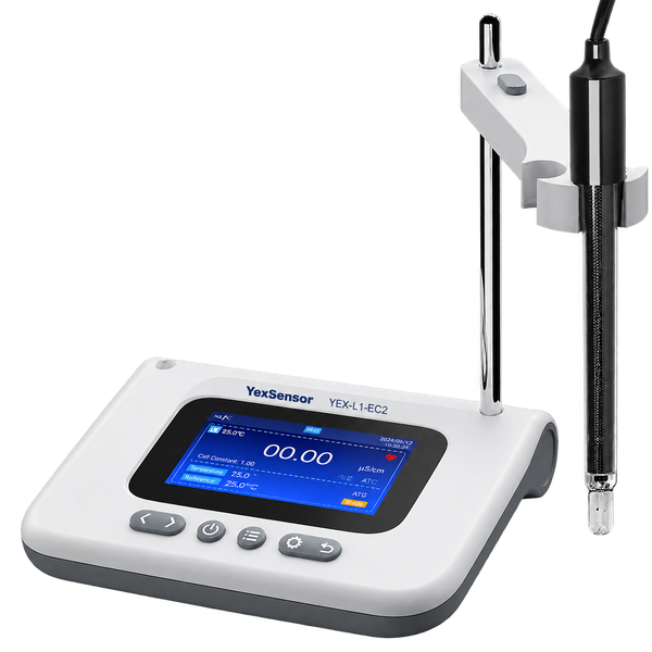

Products Description
SEO description: YexSensor YEX-L1-EC2 is a benchtop conductivity analyzer for conductivity, TDS, resistivity, salinity and temperature, with three measurement modes, USB data functions, automatic electrode recognition and IP54 protection.
Keywords: YEX-L1-EC2 benchtop conductivity analyzer, laboratory conductivity analyzer, conductivity TDS resistivity meter, salinity conductivity analyzer, USB conductivity meter, platinum-black conductivity electrode
Product Overview
YEX-L1-EC2 Benchtop Conductivity Analyzer: bring five related water-quality results, controlled measurement timing and laboratory data handling into one bench workflow.
- Five measurement outputs: conductivity, TDS, resistivity, salinity and temperature cover routine ionic-content assessment without presenting derived values as independent sensor technologies.
- Three measurement modes: continuous, equilibrium and interval modes let the operator match live observation, stable endpoint work or repeated measurements to the method.
- Laboratory control functions: automatic electrode recognition, automatic calibration, automatic or manual temperature compensation, high/low alarms, data query and USB connectivity support repeatable bench operation.
The YexSensor YEX-L1-EC2 is a benchtop conductivity analyzer for laboratories that need more control than a basic conductivity display. It works with a platinum-black conductivity electrode and presents conductivity, TDS, resistivity, salinity and temperature through a color interface. Measurement-mode selection, compensation settings, calibration, alarm thresholds and data functions are organized on the same instrument, reducing the number of disconnected steps an operator must manage during routine testing.
The analyzer is intended for surface-water testing, university and research laboratories, wastewater treatment and pharmaceutical production. Its compact 190 x 145 x 32 mm body, adjustable multiposition stand and Chinese/English interface suit shared laboratories where electrode positioning, result review and method consistency matter as much as the displayed number.
Selection Considerations and Measurement Boundaries
Select YEX-L1-EC2 when the method requires conductivity from 0 µS/cm to 20 mS/cm together with TDS, resistivity, salinity and temperature. Conductivity is the electrical measurement basis. TDS, resistivity and salinity are related result modes calculated or interpreted from the electrode response and instrument settings; they should not be counted as separate physical probes in a purchasing specification.
The documented conductivity subranges begin at 2 µS/cm and extend to 19.9 mS/cm, while the product data states an overall conductivity range of 0 µS/cm to 20 mS/cm. Use the subranges, expected sample conductivity and required uncertainty when judging method fit. The manual states a minimum resolution of 0.01 and notes that the displayed unit follows the selected parameter and range. It does not define one universal unit for that minimum-resolution statement.
USB connectivity is documented for supported data transfer, but the manual does not specify the file format, host software, USB storage capacity, communication protocol or compatibility with a particular LIMS. It also does not specify RS-485, Modbus, Ethernet, Wi-Fi or cloud connectivity. Where electronic integration is mandatory, put the target system, data format and interface requirement in the RFQ and obtain written confirmation before purchase.
IP54 protects the enclosure against limited dust ingress and splashing water under the applicable rating conditions. It does not make the analyzer immersible, washdown-rated or suitable for explosive atmospheres. The specified operating environment is 0 to 40 °C and relative humidity up to 85% RH without condensation.
Key Technical Advantages
Broader analytical view than a conductivity-only meter. Conductivity identifies ionic conduction directly, TDS supports concentration-style reporting, resistivity is useful for low-conductivity water assessment, salinity provides a percentage result and temperature supports compensation and condition review. Keeping the five outputs in one analyzer helps laboratories apply one controlled preparation and calibration routine.
Endpoint control for different sample behaviors. Continuous mode follows changing values, equilibrium mode waits for a stable endpoint and interval mode repeats measurements at a configured time interval. This allows the operator to choose a mode based on the sample and SOP instead of applying one timing rule to every test.
Temperature-compensation choice. Automatic compensation uses the connected temperature sensor; manual compensation accepts a temperature established by an external reference. The operator can therefore preserve a consistent basis when automatic sensing is appropriate or when the laboratory method requires a reference thermometer.
Electrode and calibration assistance. Automatic electrode recognition and automatic calibration reduce setting errors, while the platinum-black electrode supports the documented conductivity application. These functions still depend on clean standards, correct immersion, bubble removal, thermal equilibrium and an undamaged sensing surface.
Review and threshold tools. Stored records can be saved, deleted and queried by electrode type, test time and measured value. High- and low-limit alarms help identify values outside configured process or method limits. USB provides a documented path for supported data transfer, subject to confirmation of the required downstream format.
Technical Specifications
| Measured Quantity | Measurement Range | Minimum Resolution | Documented Error | Engineering Note |
|---|---|---|---|---|
| Conductivity | Overall: 0 µS/cm–20 mS/cm; subranges: 2–19.99 µS/cm, 20–199.9 µS/cm, 200–1999 µS/cm and 2–19.9 mS/cm | 0.01, range-dependent | Electronic unit: ±1% F.S.; instrument indication: ±1.5% F.S. | Displayed unit follows the active range. |
| TDS | 0–10,000 mg/L | 0.01 | Electronic unit: ±1% F.S. | No separate instrument indication error is stated in the manual. |
| Resistivity | 5 Ω·cm–20 MΩ·cm | 0.01 | Electronic unit: ±1% F.S. | Use electrode condition and calibration control when evaluating low-conductivity samples. |
| Salinity | 0–5% | 0.01 | Electronic unit: ±1% F.S.; instrument indication: ±0.4% F.S. | Confirm the selected salinity unit and method basis before reporting. |
| Temperature | −10–110 °C | 0.1 °C | Electronic unit: ±0.3 °C; indication: ±0.5 °C from 0 to 60 °C | The manual does not state an indication-error value outside 0–60 °C. |
| Item | Specification |
|---|---|
| Model | YEX-L1-EC2 |
| Measurement modes | Continuous, equilibrium and interval |
| Ingress protection | IP54 |
| Operating environment | 0–40 °C; relative humidity ≤85% RH, non-condensing |
| Interface language | Chinese / English |
| Power | Adapter input: 100–240 V AC, 50/60 Hz; output: DC 12 V / 1 A |
| Instrument dimensions | 190 x 145 x 32 mm (L x W x H) |
Specification note: Minimum resolution is a display characteristic and is not the same as measurement error. Evaluate suitability using range, the applicable electronic-unit or indication error, electrode condition, calibration, compensation method, sample matrix and the laboratory's uncertainty requirement together.
Measurement Modes and Workflow
| Mode | Best-Fit Use | Operating Control |
|---|---|---|
| Continuous | Observing a changing sample or following response during mixing and conditioning | Record only after the method-defined condition is reached; a changing display is not automatically a final result. |
| Equilibrium | Routine batch testing that requires a stable endpoint | Use the same stability criterion, immersion depth and compensation condition for standards and samples. |
| Interval | Repeated measurements at a configured time interval | Confirm interval settings, sample stability and data-handling requirements before the sequence starts. |
A consistent routine begins with parameter selection, electrode recognition, compensation method, measurement mode and alarm-threshold review. Calibrate or verify with a suitable standard, rinse the electrode, immerse the complete sensing area, remove bubbles and wait for thermal equilibrium. The result can then be observed, accepted or stored according to the selected mode and the laboratory procedure.
Use the same mode for calibration verification and sample work where the SOP requires comparable endpoint behavior. When changing from a high-conductivity sample to low-conductivity water, use sufficient rinsing and a clean vessel to limit carryover. When moving between sample types, recheck the selected result mode and displayed unit before accepting data.
Electrode, Compensation, and Calibration Control
The manual identifies a platinum-black conductivity electrode. Inspect the platinum-black sensing surface and glass tip before use. Do not scrape, polish, wipe aggressively or touch the coating because physical damage or contamination can change the electrode response. Rinse with deionized water, then condition with a small portion of standard or sample.
Automatic temperature compensation uses the connected temperature sensor and updates the compensated result as the sample temperature changes. Manual temperature compensation uses a user-entered value, normally based on an external reference thermometer. In either mode, the conductivity sensing area and temperature sensor must represent the same sample and should reach thermal equilibrium before the result is accepted.
For automatic calibration, use a fresh conductivity standard suitable for the expected range. Rinse with deionized water and then with the standard, immerse completely, remove bubbles and wait for stability. Start calibration from the instrument menu and confirm the result only when the display indicates stability. Verify with a fresh portion of standard after calibration; repeat the process if the result is outside the laboratory's acceptance limit.
Recalibrate after electrode cleaning or replacement, long storage, a material change in measurement range, or an unacceptable verification result. Temperature compensation does not correct contamination, exhausted standards, incorrect immersion or a damaged electrode.
Application Scenarios
| Application | Useful Outputs and Functions | Selection Check |
|---|---|---|
| Surface-water laboratories | Conductivity, TDS, salinity, temperature and equilibrium-mode endpoints | Confirm expected conductivity is within the documented range and control sample holding time. |
| University and research laboratories | Five result modes, three timing modes, Chinese/English interface and USB data functions | Confirm the required USB workflow and reporting format before method deployment. |
| Wastewater treatment laboratories | Conductivity and TDS trends, high/low alarms, interval measurements and record queries | Assess fouling, chemical compatibility and cleaning frequency for the platinum-black electrode. |
| Pharmaceutical production laboratories | Conductivity, resistivity, temperature, calibration and controlled endpoint review | Compare the specified range and errors with the applicable internal method or compendial requirement. |
Application names alone do not establish suitability. A procurement decision should connect the sample matrix, expected range, required error limit, electrode compatibility, calibration standard and reporting workflow to the corresponding specification row. For regulated work, confirm that the instrument's data functions and documentation meet the site's quality-system requirements.
Installation and Routine Measurement
Place the analyzer on a stable, level and dry bench away from direct sunlight, excessive heat, strong electromagnetic fields, corrosive vapor and vibration. Install the stand post and multiposition holder, then use the lifting button and 360-degree rotation to place the electrode vertically without touching the vessel wall or bottom. Route the cable without tension, pinching or sharp bends.
With power off, connect the conductivity electrode to the EC port. Connect the ground terminal when required by the installation, attach USB only when needed, and connect the DC 12 V / 1 A adapter last. The adapter input is 100–240 V AC at 50/60 Hz. Keep all connectors dry and do not operate damaged cables or adapters.
For routine measurement, select conductivity, TDS, resistivity, salinity or temperature; confirm the measurement mode, compensation method, alarm thresholds and electrode-recognition status; then calibrate or verify as required. Rinse and immerse the electrode, remove trapped air and allow the sample and electrode to reach thermal equilibrium. Save the result when required and rinse before the next sample.
USB, Data Management, and Alarm Functions
Data Management supports result storage, deletion and query by electrode type, test time and measured value. The manual does not state a fixed record capacity, so the product page does not assign one. Define the retention period and external record process in the laboratory SOP, especially when the instrument is shared by several users.
The rear USB port supports documented data transfer. Keep the connector dry and do not remove the USB device while data are being written. Because the manual does not state a file type, software package, USB-device specification or direct LIMS connection, confirm the exact transfer workflow in the quotation whenever electronic records are a purchase criterion.
High- and low-limit alarms compare the current result with configured thresholds. An alarm is a prompt to check the sample and method, not proof of a process failure. Verify the selected parameter and unit, threshold settings, electrode condition, calibration status and sample range before taking corrective action.
Maintenance and Troubleshooting
Rinse the electrode with deionized water after each measurement and use only cleaning methods compatible with the electrode and deposit. Never scrape or abrade the platinum-black surface or glass tip. Inspect the cable, connector, temperature sensor, stand and adapter regularly, and replace damaged components.
Clean the analyzer with a soft, slightly damp cloth. Do not use abrasive material, organic solvent or flowing water. Keep the EC, ground, USB and DC 12 V connections clean and dry. Disconnect the adapter before extended storage and store the electrode according to its supplied instructions.
For unstable readings, remove bubbles, confirm full immersion, clean the electrode, secure the connector and mix the sample gently. For high or low results, verify the selected parameter and unit, recalibrate with fresh standard and confirm that the sample is within range. If temperature compensation is wrong, check sensor immersion, automatic/manual selection and the reference thermometer. If USB transfer fails, reconnect a supported device and allow each write operation to finish.
Configuration and RFQ Checklist
Send YexSensor the sample type, expected conductivity and temperature ranges, required outputs, preferred measurement mode, daily sample count, calibration standards and acceptance limits. State whether the work emphasizes conductivity, TDS, resistivity or salinity, because range and reporting expectations differ among these outputs.
Identify acids, alkalis, solvents, oils, suspended solids or other components that may affect the platinum-black electrode or cleaning interval. Include the required power arrangement, interface language, USB transfer workflow, alarm use, documentation and service expectations. Where the analyzer must exchange data with a computer, LIMS or other system, define the receiving system and required file or protocol instead of assuming compatibility.
For regulated or critical methods, provide the current SOP or applicable standard, required uncertainty or acceptance error, calibration frequency, verification material, record-retention requirement and approval process. This information lets the supplier determine whether the documented ranges and functions fit the method before the order is finalized.
Order Confirmation, Supply Boundary, and After-Sales Information
| Confirmation Item | What to Specify | Why It Matters |
|---|---|---|
| Analyzer model | YEX-L1-EC2 | Prevents substitution with the EC1 meter or a portable product. |
| Measurement requirement | Required outputs, expected ranges, temperature and sample matrix | Connects the application to the documented specification limits. |
| Electrode configuration | Platinum-black conductivity electrode, cable and sample compatibility | Electrode condition and compatibility directly affect measurement performance. |
| Calibration and verification | Standards, frequency, acceptance limits and traceability documents | Defines the quality-control workflow before commissioning. |
| USB and records | Required transfer method, file format, host device and retention process | The manual confirms USB but does not define every integration detail. |
| Power and installation | 100–240 V AC supply, bench environment and grounding need | Confirms safe use of the DC 12 V / 1 A adapter and rear connections. |
| Accessories and documents | Stand, electrode, adapter, cables, certificates and language | Prevents assumptions about the final package and documentation set. |
| Warranty and service | Applicable warranty terms, support scope and spare-part expectations | Coverage is governed by the signed sales agreement. |
The manual identifies the analyzer, platinum-black conductivity electrode, stand, cables and adapter as the operating set, but the final supplied components must follow the signed sales order and final packing list. Inspect the delivered instrument, display, connectors, stand, electrode and ordered accessories before use. For support, provide the model, serial number, purchase information, electrode details, standard, verification result and a clear description of the problem.
Frequently Asked Questions
1. What does the YEX-L1-EC2 measure?
It provides conductivity, TDS, resistivity, salinity and temperature results. Conductivity covers an overall documented range of 0 µS/cm to 20 mS/cm, TDS covers 0 to 10,000 mg/L, resistivity covers 5 Ω·cm to 20 MΩ·cm, salinity covers 0 to 5%, and temperature covers −10 to 110 °C. Select the product only after matching the relevant range and documented error to the method.
2. How is EC2 different from the YEX-L1-EC1?
EC2 is positioned as a benchtop analyzer with conductivity, TDS, resistivity, salinity and temperature, plus continuous, equilibrium and interval modes, automatic electrode recognition, alarms, USB connectivity, Chinese/English menus and IP54 protection. EC1 has a different range structure and feature set. They should be selected by method requirements, not treated as interchangeable model numbers.
3. Are TDS, resistivity and salinity separate sensors?
No separate probes are specified for those result modes. The analyzer uses the platinum-black conductivity electrode response with the selected parameter and instrument settings. For defensible reporting, record the active mode, unit, calibration condition and compensation method rather than describing each displayed value as a separate sensor measurement.
4. Which measurement mode should a laboratory use?
Use equilibrium mode for stable endpoint work, continuous mode when observing a changing sample, and interval mode for repeated measurements at configured times. The laboratory SOP should define the mode, stability rule, interval, immersion depth and acceptance criteria. Using the same controls for standards and samples improves comparability.
5. Does the 0.01 minimum resolution mean accuracy is ±0.01?
No. Resolution is the smallest stated display increment and its unit follows the selected parameter and range. Conductivity electronic-unit error is ±1% F.S. and instrument indication error is ±1.5% F.S.; other parameters have their own documented errors. Base procurement decisions on the applicable error, range, sample matrix and calibration practice, not resolution alone.
6. How should automatic and manual temperature compensation be selected?
Use automatic compensation when the connected temperature sensor is immersed in the same sample and verified for correct response. Use manual compensation when the method requires a temperature from an external reference thermometer. In both cases, wait for thermal equilibrium and remember that compensation cannot correct contamination, bubbles or poor calibration.
7. Can the USB port connect directly to a LIMS, PLC or Modbus network?
The manual documents USB for supported data transfer but does not specify a direct LIMS workflow, PLC integration, RS-485, Modbus, Ethernet, Wi-Fi or cloud communication. If integration is mandatory, state the target system, file format and protocol in the RFQ and obtain written compatibility confirmation before ordering.
8. What information should be included in an RFQ for YEX-L1-EC2?
Provide sample type, expected conductivity and temperature, required TDS/resistivity/salinity outputs, required error limit, measurement mode, sample count, standards, calibration frequency, USB workflow, power supply, electrode compatibility concerns, certificates, language and service expectations. These inputs allow YexSensor to confirm method fit and define the supplied package without hidden assumptions.
Summary
YEX-L1-EC2 is designed for laboratories that need conductivity, TDS, resistivity, salinity and temperature in a controlled benchtop workflow. Its practical strengths are three measurement modes, automatic electrode recognition and calibration, automatic or manual temperature compensation, high/low alarms, searchable records, USB data functions, a bilingual interface, IP54 protection and an adjustable multiposition stand.
The selection boundary is equally clear: use the documented subranges and errors rather than resolution alone, protect the platinum-black electrode, operate within 0–40 °C and non-condensing humidity, and do not assume RS-485/Modbus or a particular USB file format. Send YexSensor the sample matrix, expected range, required uncertainty, measurement mode, calibration and data workflow. Those project inputs are the fastest way to confirm whether EC2 fits the method and what the final quotation must include.

