


 Chinese
 Spanish
 French
 Russian
 German
 Portuguese
 Indonesian
 Thai
Thai Vietnamese
 Arabic


Products Description
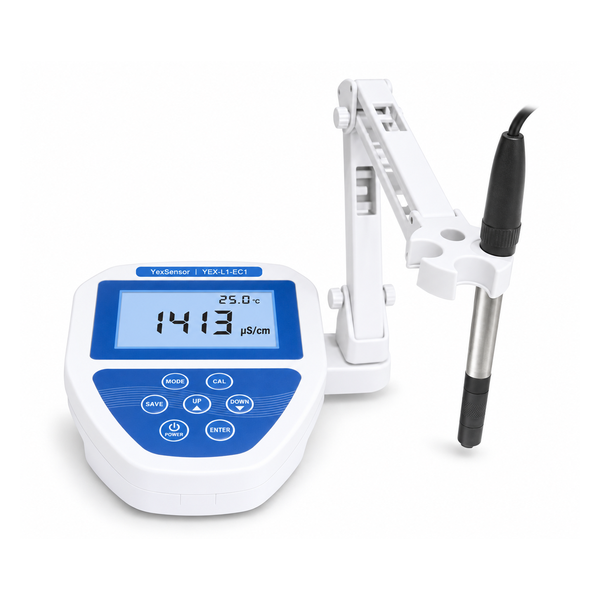
YEX-L1-EC1 Benchtop Conductivity Meter: one laboratory platform for conductivity, TDS, salinity, and temperature measurement
- Wide conductivity coverage: 0.0000 µS/cm–400.0 mS/cm across supported conductivity cells with constants of 0.01, 0.1, 1, and 10 cm⁻¹.
- Four measurement outputs: conductivity and temperature measurement, plus TDS calculated with a factor of 0.5 and salinity calculated with a SAL coefficient of 0.6.
- Routine laboratory control: automatic range switching, automatic temperature compensation, stable-measurement indication, 256 stored records, and battery or adapter power.
Product Overview
The YexSensor YEX-L1-EC1 is a compact benchtop conductivity meter for laboratories that need to cover low-conductivity water, routine aqueous samples, and higher-conductivity process solutions with a documented cell-selection method. The meter measures conductivity and temperature and provides derived TDS and salinity modes. Its large backlit LCD, stable-measurement indication, automatic range switching, 256-result memory, and adjustable electrode stand support repeated bench work without occupying excessive space.
The instrument supports conductivity-cell constants of K = 0.01, 0.1, 1, and 10 cm⁻¹. The selected cell constant determines the usable conductivity range and display resolution, so the meter and cell must be specified as one measurement system. Typical users include water and wastewater laboratories, research institutes, universities, aquaculture facilities, food and beverage plants, pharmaceutical laboratories, power and electronics facilities, petrochemical operations, municipal laboratories, and general industrial quality-control teams.
Selection Considerations and Measurement Boundaries
Conductivity is measured directly; TDS and salinity are derived modes
The primary measured quantity is conductivity. TDS mode converts the conductivity response using the specified factor of 0.5, while salinity mode uses the specified SAL coefficient of 0.6. These outputs are useful for routine trending when the selected conversion model fits the sample, but they are not independent gravimetric TDS or composition-specific salinity analyses. Buyers should state whether the project requires direct conductivity reporting, derived TDS or salinity values, or all three modes.
The overall range is shared across several cell constants
The published overall conductivity span is 0.0000 µS/cm–400.0 mS/cm, but no single conductivity cell covers every listed subrange. The ordered cell constant must match the expected sample conductivity and required resolution. For example, the table documents K = 0.01 cm⁻¹ ranges from 0.0000–400.0 µS/cm, while K = 10 cm⁻¹ extends to 400.0 mS/cm. State the expected minimum, normal, and maximum conductivity in the RFQ so the cell can be selected correctly.
Pure-water work requires an explicitly configured cell
The manual identifies a configured K = 0.1 cm⁻¹ conductivity-cell range for pure-water or high-purity-water measurement. Low-conductivity work is especially sensitive to contamination, air exposure, temperature differences, bubbles, handling, and cell condition. Confirm the expected water grade, target range, sampling vessel, verification standard, and cell configuration before ordering rather than assuming that a general-purpose cell will meet the method.
Key Technical Advantages
Automatic scanning and range switching
After the cell is immersed, the meter scans the current conductivity and selects an appropriate supported range. The displayed resolution changes with the selected range, from 0.0001 µS/cm in the lowest documented K = 0.01 cm⁻¹ range to 0.1 mS/cm in the highest K = 10 cm⁻¹ range. Automatic switching reduces manual range selection, while the operator remains responsible for installing the correct cell constant and maintaining consistent immersion conditions.
Automatic temperature compensation and stable-result indication
Automatic temperature compensation supports routine comparison when the compatible temperature sensing arrangement is connected and immersed correctly. A stable-measurement icon helps the operator wait for signal and temperature stabilization before recording a result. Compensation does not eliminate sample chemistry changes with temperature, so laboratories should still follow the temperature conditions required by their method.
Strong interference resistance and controlled bench geometry
The manual describes strong interference resistance and precise measurement for routine professional work. The adjustable stand can be installed on either side of the meter and keeps the conductivity cell vertical, approximately 90 degrees to the bench. Locating the sensing area away from the vessel wall and bottom, removing trapped bubbles, and keeping the cable relaxed all reduce avoidable measurement variation.
Local storage and flexible power
Up to 256 measurement records can be saved for later review on the instrument. Power is supplied by four AAA batteries or the specified adapter with 100–200 V AC input, and stated battery life is more than 500 hours under the documented product conditions. The manual does not specify USB export, RS-485, Modbus, Bluetooth, Wi-Fi, cloud, LIMS, or SCADA communication, so projects requiring electronic data transfer should define a separate validated workflow or choose a product with documented connectivity.
Technical Specifications
The measurement matrix below places each reported quantity on one row so range, resolution, error limits, and conversion conditions can be compared without repeated category labels.
Measurement Performance
| Measured Quantity | Measurement Range | Display Resolution | Accuracy / Indication Error | Conversion / Selection Note |
|---|---|---|---|---|
| Conductivity | 0.0000 µS/cm–400.0 mS/cm | 0.001 µS/cm–0.1 mS/cm, range-dependent | ±0.5% F.S. | Usable subrange depends on the selected cell constant. |
| TDS | 0.0000–200.0 ppt | 0.001 mg/L–0.1 g/L | ±0.5% F.S. | Derived from conductivity using conversion factor 0.5. |
| Salinity | 0.0–260.0 g/L | 0.1 g/L | ±0.5% F.S. | Derived from conductivity using SAL coefficient 0.6. |
| Temperature | −10.0–110.0 °C | 0.1 °C | ±0.2 °C | Supports automatic temperature compensation. |
Instrument Specifications
| Item | Specification |
|---|---|
| Model | YEX-L1-EC1 |
| Power source | Four AAA batteries or adapter with 100–200 V AC input |
| Battery life | >500 hours |
| Operating environment | −5–60 °C; relative humidity <90% |
| Data storage | 256 measurement records |
| Dimensions / weight | 150 x 200 x 60 mm (W x L x H); 660 g |
Cell Constant Selection and Range Coverage
Select the conductivity cell by expected range rather than by the meter's overall maximum. The grouped table shows every automatic subrange and its matching display resolution while presenting each cell constant only once.
| Cell Constant | Measurement Range | Display Resolution |
|---|---|---|
| K = 0.01 cm⁻¹ | 0.0000–0.4000 µS/cm | 0.0001 µS/cm |
| 0.000–4.000 µS/cm | 0.001 µS/cm | |
| 0.00–40.00 µS/cm | 0.01 µS/cm | |
| 0.0–400.0 µS/cm | 0.1 µS/cm | |
| K = 0.1 cm⁻¹ | 0.00–40.00 µS/cm | 0.01 µS/cm |
| 0.0–400.0 µS/cm | 0.1 µS/cm | |
| 0–4000 µS/cm | 1 µS/cm | |
| K = 1 cm⁻¹ | 0–400.0 µS/cm | 0.1 µS/cm |
| 0–4000 µS/cm | 1 µS/cm | |
| 0.0–40.00 mS/cm | 0.01 mS/cm | |
| K = 10 cm⁻¹ | 0–4000 µS/cm | 1 µS/cm |
| 0–40.00 mS/cm | 0.01 mS/cm | |
| 0–400.0 mS/cm | 0.1 mS/cm |
When the sample range crosses the practical coverage of one cell, define whether more than one cell or a different measurement method is required. The sales order should state the selected cell type, constant, connector, cable requirement, quantity, and any temperature-sensing arrangement.
Application Scenarios
Pure-water and high-purity-water laboratories
Use the configured K = 0.1 cm⁻¹ range identified in the manual, with careful control of vessels, rinsing, air exposure, temperature equilibration, and verification standards. Provide the expected conductivity range and water grade so the final cell configuration can be confirmed.
Drinking water, wastewater, and municipal testing
Conductivity supports ionic-strength trending, treatment checks, source comparison, and routine process monitoring. TDS mode can provide a factor-based operational value when the fixed 0.5 conversion is suitable for the laboratory method; otherwise report conductivity directly.
Aquaculture, agriculture, and environmental monitoring
Conductivity and derived salinity values help compare water sources, ponds, nutrient solutions, and environmental samples. Use the same cell constant, immersion depth, temperature-compensation condition, stabilization rule, and sampling procedure when comparing locations or time periods.
Food, beverage, brewing, and pharmaceutical laboratories
The meter can support water checks, cleaning verification, raw-material comparison, and process-solution screening within the documented range. Confirm that the conductivity cell materials, cleaning procedure, and conversion assumptions are compatible with the sample matrix and the applicable laboratory method.
Power, electronics, petrochemical, and industrial quality control
The broad range supports low-conductivity water and higher-conductivity process samples when the proper cell constant is installed. Separate cells or procedures may be needed to avoid contamination transfer between very clean water and concentrated industrial samples.
Research institutes and universities
Multiple measurement modes, automatic range switching, selectable cell constants, and local result storage support teaching and method-development work. Experimental reports should identify the cell constant, mode, compensation condition, standard, and conversion coefficient used for every result.
Installation and Routine Measurement
Place the meter on a stable, dry, level bench away from direct sunlight, strong electromagnetic fields, heat, vibration, and corrosive vapors. Install the electrode stand on the left or right side and adjust the holder so the conductivity cell remains vertical. With the meter switched off, connect the conductivity cell and the temperature sensor if it is separate. Keep connectors, the battery compartment, and cables clean and dry.
Install four AAA batteries with the correct polarity or connect the specified adapter to a 100–200 V AC supply. Do not mix old and new batteries. Before measurement, confirm that the cell constant marked on the cell matches the meter setting and expected sample range. Rinse with deionized water, then with a small portion of sample or standard. Fully immerse the sensing area, keep it away from the vessel wall and bottom, and remove trapped air bubbles without striking or scraping the sensor.
Select conductivity, TDS, or salinity mode as required. For conductivity, calibrate or verify with a suitable fresh standard. Wait for temperature and signal stability and the stable-measurement indication before recording or saving the result. Rinse between samples and after use. Maintain the same cell setting, immersion depth, compensation condition, and stabilization criterion for standards and samples.
Calibration and Quality Control
Use a fresh conductivity standard that is suitable for the installed cell constant and the expected measurement range. The manual does not prescribe one universal standard concentration, so the laboratory must select and document an appropriate standard and acceptance limit. Standards should be clean, uncontaminated, and temperature-equilibrated; never return used solution to the original container.
Confirm conductivity mode and the correct cell constant, rinse the cell with deionized water and then with the standard, immerse the sensing area fully, remove bubbles, and wait for temperature and reading stability. Enter calibration with the front-panel CAL control and follow the displayed prompts. After calibration, rinse and verify in a second portion of fresh standard. Repeat the calibration when verification falls outside the laboratory's acceptance limit.
Recalibrate after cell replacement, cleaning, extended storage, a cell-constant change, or an unacceptable verification result. For traceable work, record the standard identity, lot, stated value, temperature, cell constant, calibration date, verification result, operator, and acceptance decision. The meter's ±0.5% F.S. indication error must be considered together with standard uncertainty, cell condition, temperature control, sample handling, and method requirements.
Records, Modes, and Operating Controls
| Function | Documented capability | Laboratory use |
|---|---|---|
| Measurement modes | Conductivity, TDS, and salinity | Select the reporting mode required by the method |
| Automatic range switching | Scans the current value and selects a supported range | Resolution follows the active range and installed cell constant |
| Temperature compensation | Automatic | Connect and immerse the compatible temperature sensing arrangement |
| Stable-measurement indication | Icon indication | Wait for stability before recording or saving a result |
| Record memory | 256 measurement records | Confirm that required results are saved and review memory routinely |
| Power | Four AAA batteries or specified adapter | Confirm destination voltage and plug configuration before shipment |
| Digital communication | Not specified in the manual | Do not assume USB, RS-485, Modbus, Bluetooth, Wi-Fi, cloud, LIMS, or SCADA connectivity |
TDS uses a conversion factor of 0.5 and salinity uses a SAL coefficient of 0.6. Keep the selected mode and conversion basis with the reported result so values can be interpreted correctly.
Maintenance and Troubleshooting
Rinse the cell with deionized water after each measurement. Remove deposits with a cleaning solution compatible with both the cell materials and the contamination. Do not scrape, abrade, or deform sensing surfaces. Inspect the cable, connector, sensing area, and temperature sensor regularly, and replace damaged components. Clean the meter only with a soft, slightly damp cloth; do not use abrasive materials, organic solvents, flowing water, or immersion.
For unstable readings, check bubbles, immersion, cleanliness, the connector, sample uniformity, and temperature stability. For values that are too high or low, confirm the installed cell constant, meter setting, mode, contamination condition, and suitable range. Slow response can indicate deposits, very low sample conductivity, a large temperature difference, or cell damage. Calibration failure requires a fresh suitable standard, correct cell constant, full immersion, bubble removal, and sufficient stabilization. If TDS or salinity appears unsuitable, confirm the fixed factor of 0.5 or coefficient of 0.6 and determine whether the conversion model fits the sample.
Configuration and RFQ Checklist
For a technically complete quotation, provide the sample type and matrix; minimum, normal, and maximum conductivity; required conductivity, TDS, salinity, and temperature outputs; expected accuracy and reporting resolution; pure-water or high-purity-water requirement; daily sample count; sample temperature; cell material or chemical-compatibility constraints; cable and connector needs; preferred power arrangement; destination voltage and plug; required standards and cleaning solutions; quantity; delivery destination; and documentation requirements.
Also state whether one cell must cover the routine range or whether separate low- and high-conductivity cells are acceptable. Identify the laboratory's calibration standard, verification interval, acceptance limit, and data-recording process. Because the manual documents local storage but no digital export interface, electronic data-transfer requirements must be resolved before ordering.
Order Confirmation, Supply Boundary, and After-Sales Information
| Item | Manual-defined status | Order confirmation note |
|---|---|---|
| YEX-L1-EC1 meter | Primary product | Confirm model, quantity, destination, and serial-number documentation |
| Conductivity cell | Configuration-dependent | Specify cell type, constant, sample compatibility, connector, cable, and quantity |
| Temperature sensor | Separate if configured that way | Confirm the supplied temperature-sensing arrangement |
| Electrode stand | Referenced during unpacking | Confirm holder configuration and supplied quantity |
| Power adapter | Specified power option | Confirm rating and destination plug |
| AAA batteries | Four required for battery operation | Confirm whether batteries are supplied or sourced locally |
| Standards and cleaning solutions | Application-dependent | List each required solution, value, volume, and quantity |
| Documentation | Order-dependent | Confirm manual, certificate, language, packing list, and acceptance records |
Supplied accessories and quantities must follow the signed sales order and final packing list; the manual does not define one universal fixed package for every cell configuration. Inspect the meter, cell, stand, cables, adapter, and documents on receipt and report transport damage or discrepancies before use.
Warranty coverage and service conditions are governed by the applicable sales agreement. Damage caused by unauthorized disassembly, incorrect power supply, unsuitable operating conditions, misuse, improper storage or transport, consumable conductivity cells, or force majeure may be excluded from free warranty service. For support, provide the model, serial number, purchase information, cell type and constant, calibration standard, verification result, and a clear description of the problem.
Frequently Asked Questions
1. What does the YEX-L1-EC1 measure?
It measures conductivity from 0.0000 µS/cm–400.0 mS/cm across supported conductivity cells and measures temperature from −10.0–110.0 °C. It also displays derived TDS from 0.0000–200.0 ppt using a factor of 0.5 and derived salinity from 0.0–260.0 g/L using a SAL coefficient of 0.6. The ordered cell constant determines the usable conductivity subrange.
2. Are conductivity, TDS, and salinity three independent sensors?
No. Conductivity is the directly measured electrical parameter. TDS and salinity are calculated display modes based on the conductivity response and the documented factors. Use them for methods where those conversion assumptions are acceptable. If the project requires gravimetric TDS or composition-specific salinity, define that separate analytical method in the procurement specification.
3. Which conductivity-cell constant should be selected?
Select it from the expected minimum and maximum conductivity, required resolution, sample matrix, and cell compatibility. The documented choices are K = 0.01, 0.1, 1, and 10 cm⁻¹, with different subranges. Do not select only from the meter's overall 400.0 mS/cm maximum. Send YexSensor the actual sample range so the ordered cell and meter setting can be matched.
4. Can one cell cover the complete 0.0000 µS/cm–400.0 mS/cm range?
No single listed cell covers the entire overall range. K = 0.01 cm⁻¹ covers documented ranges up to 400.0 µS/cm, K = 0.1 cm⁻¹ up to 4000 µS/cm, K = 1 cm⁻¹ up to 40.00 mS/cm, and K = 10 cm⁻¹ up to 400.0 mS/cm. A project spanning widely separated ranges may require more than one cell or separate procedures.
5. Is the meter suitable for pure or high-purity water?
The manual identifies a configured K = 0.1 cm⁻¹ range for pure-water or high-purity-water measurement. Confirm the actual target range and method before ordering. Low-conductivity results are highly sensitive to contamination, air exposure, temperature, bubbles, vessel cleanliness, and handling, so verification and sampling practice are as important as the displayed resolution.
6. Does the finest resolution mean the accuracy is equally small?
No. Resolution is the smallest displayed increment for a particular range, while the stated conductivity indication error is ±0.5% F.S. Measurement uncertainty also depends on the conductivity cell, cell constant, standard uncertainty, temperature compensation, calibration, sample handling, contamination, and stabilization. Acceptance criteria should use the full measurement system, not display digits alone.
7. Can the 256 records be exported by USB or sent by RS-485 or Modbus?
The manual documents storage and later review of 256 measurement records on the meter. It does not specify USB export, RS-485, Modbus, Bluetooth, Wi-Fi, cloud, LIMS, or SCADA communication. If electronic transfer is mandatory, establish a separate validated recording process or select an analyzer with a documented interface before placing the order.
8. What information is required for a quotation?
Provide the sample matrix, expected conductivity range, required resolution and accuracy, conductivity/TDS/salinity reporting needs, pure-water requirement, sample temperature, daily workload, preferred cell constant or selection request, cell-material compatibility, cable and connector requirements, calibration standard, power and plug type, quantity, destination, and documents. YexSensor can then confirm the meter, cell, stand, temperature arrangement, adapter, solutions, and supply boundary.
Summary
The YEX-L1-EC1 is suited to laboratories that need one compact benchtop platform for conductivity and temperature measurement plus factor-based TDS and salinity reporting. Its main strengths are broad multi-cell range coverage, automatic range switching, automatic temperature compensation, stable-measurement indication, 256-result storage, and flexible battery or adapter power. The key selection boundaries are the conductivity-cell constant, required subrange and resolution, conversion assumptions, sample compatibility, calibration standard, and the absence of documented digital communication interfaces.
For an application-matched proposal, send YexSensor the sample matrix, minimum and maximum conductivity, required outputs, pure-water requirement, temperature conditions, calibration and verification plan, daily sample count, cell and cable constraints, power preference, destination, quantities, and documentation needs. These inputs allow the cell constant, measurement range, accessories, supply list, and acceptance procedure to be confirmed before shipment.

