


 Chinese
 Spanish
 French
 Russian
 German
 Portuguese
 Indonesian
 Thai
Thai Vietnamese
 Arabic


Products Description
YEX-S1PRO-TDS Online Total Dissolved Solids Sensor: Stable TDS and Temperature Monitoring for Industrial Water Projects
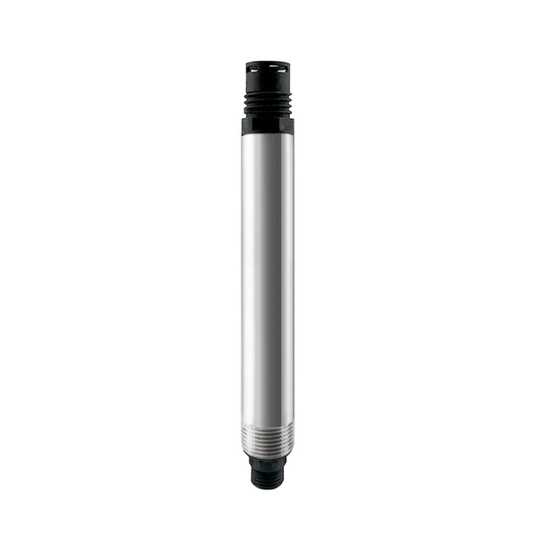
YEX-S1PRO-TDS Online Total Dissolved Solids Sensor Product Introduction
YexSensor YEX-S1PRO-TDS is designed for continuous TDS and temperature measurement in water quality systems. Unlike the four-parameter YEX-S1PRO-ECT4 configuration, this page is positioned for projects that primarily require TDS plus the temperature channel used for compensation and process evaluation.
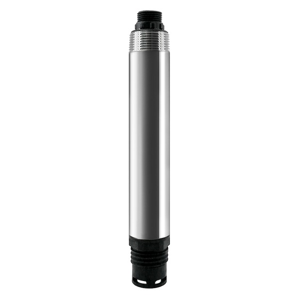
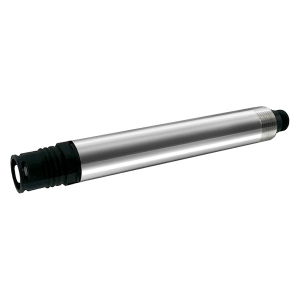
The sensor uses a high-stability titanium electrode, 316L stainless steel + ABS housing and IP68 protection. Three selectable range levels support different clean-water, process-water, wastewater and environmental applications, while customized ranges can be confirmed for OEM and engineering projects.
Standard RS-485 Modbus RTU communication supports PLC, RTU, data logger, SCADA and IoT gateway integration. Optional 4-20mA output can be selected for analog control systems. RS-485 and 4-20mA are alternative configurations and should be confirmed when ordering.
S1 PRO Positioning and Engineering Advantages
YEX-S1PRO-TDS provides continuous total dissolved solids data for treatment comparison, membrane-system trends and water-quality alarms. Temperature is included as a standard measured channel in the sensor and reaches +/-0.1 C accuracy, supporting automatic compensation and allowing the control system to read the process temperature independently.
The titanium electrode, 10-second response, 316L stainless steel structure and digital communication make the sensor suitable for integrators who need stable online data, compact installation and clear Modbus mapping. The NPT 3/4 thread supports immersion, pipe and tank mounting without changing the sensing principle.
How to Interpret the Measurement
Online TDS is derived from the conductivity response using a conversion relationship. It is valuable for continuous trends, treatment comparison and alarm control, but it is not the same analytical method as gravimetric total dissolved solids testing. The conversion factor depends on the ionic composition of the water, so commissioning should compare the online result with the project reference method and document any site-specific factor.
Core Technical Highlights
Dedicated TDS positioning: The product page and selection data focus on TDS, while temperature remains included for compensation and monitoring.
Three selectable ranges: 0-3000 / 0-10000 / 0-30000 ppm, customizable.
High measurement accuracy: TDS accuracy reaches +/-1.5%, with temperature accuracy of +/-0.1 C and 10-second response.
Titanium electrode: The high-stability titanium sensing element supports reliable long-term online measurement.
316L stainless steel + ABS: The compact IP68 housing supports demanding immersion and industrial field installations.
RS-485 / optional 4-20mA: Select Modbus RTU for digital systems or optional 4-20mA for analog systems.
Automatic temperature compensation: Integrated temperature data helps reduce the influence of water-temperature variation on the primary reading.
Application Scenarios and System Integration
YEX-S1PRO-TDS can be connected to PLC, SCADA, RTU, telemetry and water-quality IoT systems. The value of the sensor is not simply continuous display; it is the ability to connect a measured change to an operating decision, alarm, sampling action or control response.
Reverse-osmosis performance monitoring
Compare feed, concentrate and permeate TDS trends to reveal membrane loading, rejection deterioration, valve leakage or abnormal blending. Use properly ranged sensors at each point because feed and permeate may differ by orders of magnitude.Drinking-water and purified-water systems
Provide continuous dissolved-solids trend data for source change, filter performance and product-water alarms. Online TDS is useful for operational screening but does not replace required microbiological or ion-specific compliance tests.Industrial reuse and rinse-water control
Determine whether reclaimed or rinse water remains within a process-specific dissolved-solids window. The signal can support reuse/divert decisions and help prevent salt carryover into sensitive production stages.Municipal and environmental monitoring
Track broad changes in dissolved mineral load and trigger investigation after unusual events. Interpret the trend together with conductivity, temperature and laboratory chemistry rather than treating TDS as a complete pollution index.
For project selection, provide the expected minimum, normal and maximum value, water type, temperature, pressure, installation method, cable length and required output. This helps match the correct range without sacrificing useful resolution.
Range Selection, Data Quality and Procurement Boundaries
Range Selection
Use 0-3000 ppm for many drinking-water, purified-water and moderate process-water applications; 0-10000 or 0-30000 ppm may be needed for concentrate, wastewater or high-mineral streams. For an RO system, do not assume one range is suitable for both feed and permeate. Select each point from actual water analysis and the smallest value change that operators need to detect.
Installation and Data Quality Risks
Changing ionic composition can change the relationship between conductivity and calculated TDS even when the true gravimetric mass is similar. Fouling, bubbles and incomplete immersion also affect stability. Establish a commissioning correlation, clean the titanium electrode routinely and investigate sustained deviation rather than applying an arbitrary correction.
Information Required for a Reliable Quotation
Provide the water source and process purpose, recent laboratory results, expected minimum/normal/maximum TDS, temperature and pressure, pH, major dissolved chemicals, cleaning agents, installation drawing, flow condition, cable length, controller model, required output, Modbus settings, quantity and destination. State whether the reading will be used for display, alarm, automatic control, reporting or treatment-performance calculation.
PLC, SCADA and Alarm Strategy
Map the primary TDS value and temperature as separate engineering tags. Configure communication-loss, out-of-range and rate-of-change alarms independently from the process high/low limits, because a frozen or missing signal should not be interpreted as normal water quality. Use a short validation delay or moving average only where process dynamics allow it; excessive filtering can hide a genuine step change. Store the raw reading, compensated reading basis, device address, range configuration and maintenance status in the commissioning record so future troubleshooting does not depend on undocumented controller scaling.
Commissioning and Acceptance
Before acceptance, verify wiring polarity, device address, baud rate, register order, engineering unit and decimal scaling. Compare the stabilized online reading with a suitable reference at low, normal and high points within the selected range, then document the water temperature and reference method. Confirm that PLC alarms, historical trends and any control interlocks respond correctly to a simulated value change or approved process test. Acceptance should cover the complete measurement loop from sensor to HMI, not only the probe output.
YEX-S1PRO-TDS Technical Specifications
| Item | Specification |
|---|---|
| Product model | YEX-S1PRO-TDS |
| Measured parameters | TDS and temperature |
| TDS range | 0-3000 / 0-10000 / 0-30000 ppm, customizable |
| Resolution | 1 ppm |
| Accuracy | TDS: +/-1.5%; temperature: +/-0.1 C |
| Response time | 10 s |
| Output signal | RS-485 (Modbus RTU protocol) / Optional 4-20mA, select one |
| Power supply / consumption | 12-24 VDC / approx. 0.4 W |
| Electrode | High-stability titanium electrode |
| Housing material | 316L stainless steel + ABS |
| Protection grade | IP68 |
| Operating environment | 0-50 C, non-freezing; pressure < 0.2 MPa |
| Temperature compensation | Automatic temperature compensation |
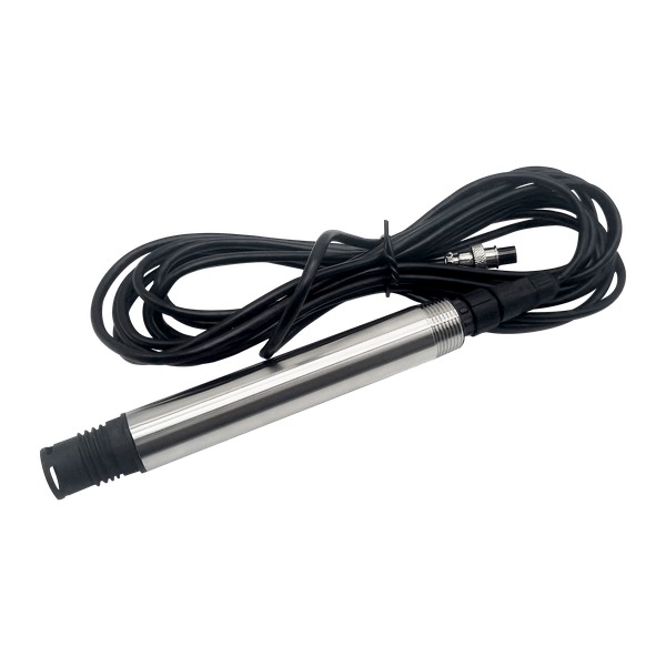
| Cable | 5 m four-core shielded cable |
| Installation | Immersion, pipe or tank installation; NPT 3/4 thread |
Installation Guidance and Electrical Connection
Installation Position
Install the sensor by immersion or through the NPT 3/4 thread in a pipe or tank. Keep at least one-third of the probe immersed and avoid upside-down or horizontal installation. Maintain an inclination greater than 15 degrees where required, and avoid severe bubbles, deposits or direct impact on the electrode.
Electrical Wiring
Connection reference: pin 1/red is power positive, pin 2/black is power negative, pin 3/green is RS485-B, pin 4/yellow is RS485-A, and pin 5 is optional 4-20mA output. Wire colors may vary by batch; use connector markings or pin numbers as the final reference.
Maintenance and Calibration
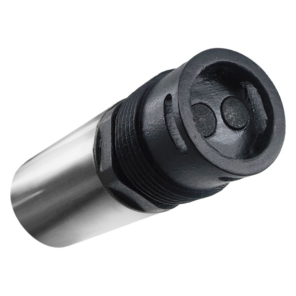
Keep the titanium electrode, terminals and aviation connector clean. Use a soft-bristled brush to remove deposits without scratching the sensing surface. Inspect cable seals and verify the reading against a suitable reference when site conditions change.
The sensor is factory calibrated. Recalibrate only when necessary. Zero-point and slope calibration are performed through the communication protocol using air or purified water and a known conductivity-based reference solution. Follow the protocol supplied with the delivered batch.
Frequently Asked Questions
Q1: Is online TDS the same as gravimetric total dissolved solids testing?
A1: No. This sensor derives online TDS from the conductivity response using a conversion relationship, while the gravimetric method determines residue after a defined laboratory procedure. Online TDS is highly useful for continuous trends, alarms and treatment comparison, but regulatory or contractual results should follow the specified reference method. Establish a site correlation during commissioning when numerical agreement is important.
Q2: How should the TDS range be selected for an RO system?
A2: Select each measurement point separately from actual water data. Feed, concentrate and permeate can differ by orders of magnitude, so one range may not provide useful resolution at every point. The 0-3000 ppm range suits many product-water and moderate feed applications, while 0-10000 or 0-30000 ppm may be needed for concentrate, wastewater or mineralized sources. Include cleaning and upset conditions in the maximum value.
Q3: Can TDS data be used to calculate membrane rejection?
A3: It can support an operational rejection trend when feed and permeate sensors use compatible units, conversion settings, temperature basis and synchronized readings. The calculation is commonly based on the relative difference between feed and permeate values. Treat it as a process indicator rather than a laboratory certificate, and investigate valve leakage, blending, sensor fouling and range mismatch before concluding that membrane performance has deteriorated.
Q4: Why can the TDS conversion factor vary between water sources?
A4: Different dissolved ions contribute differently to conductivity, so two waters with the same gravimetric dissolved-solids mass may not produce the same electrical response. A factor established for one stable water source may be inaccurate after a source or chemical-treatment change. Compare the online result with the project laboratory method and document the factor or acceptance relationship used at commissioning.
Q5: Where should TDS sensors be installed in a treatment process?
A5: Install at representative, continuously wetted points with adequate mixing and sufficient distance from dosing, membrane flush discharge or recycle junctions. For performance comparison, use comparable installation conditions and synchronized data at feed, product and concentrate points. Avoid bubbles, deposits, dead legs and partial immersion because these can create unstable or biased readings.
Q6: How should TDS and temperature be integrated into PLC or SCADA?
A6: Create separate tags for TDS, temperature and communication status, and confirm unit and decimal scaling from sensor to HMI. Configure process alarms, communication-loss alarms and rate-of-change checks independently. For diversion or product-water interlocks, apply a short validation period consistent with process transit time, then function-test the complete loop rather than checking only the local reading.
Q7: When is optional 4-20mA suitable, and when is RS-485 preferable?
A7: Optional 4-20mA is suitable for a conventional point-to-point analog input where only one scaled process value is required. RS-485 Modbus is preferable for exact digital values, temperature access, multidrop networks and easier integration with data loggers or IoT gateways. They are alternative order options, so define the required output and TDS full-scale value before manufacture.
Q8: What should be checked when the TDS reading appears too high or too low?
A8: First confirm the selected range, engineering unit, temperature basis, conversion relationship and PLC scaling. Then inspect for bubbles, incomplete immersion, coating and abnormal process mixing. Compare a stabilized sample with the agreed reference method at the same time and temperature. Recalibrate only after installation, reference and composition effects have been excluded and persistent sensor drift is confirmed.
Quality Assurance and After-sales Service
YexSensor is committed to providing a reliable product experience.
Strict quality inspection: Each product goes through a standardized inspection process and a 72-hour aging test to help ensure a defect rate below 2%.
One-year warranty: A one-year after-sales warranty is provided from the date of sale, excluding man-made damage or improper use.
Standard cable configuration: The standard configuration includes a 5 m four-core shielded cable. Other accessories are confirmed according to the order and packing list.

