


 Chinese
 Spanish
 French
 Russian
 German
 Portuguese
 Indonesian
 Thai
Thai Vietnamese
 Arabic

Direct answer: oil depot wastewater monitoring should separate three decisions: detect an oil event before treatment, protect the treatment process from a shock load, and verify the final discharge or reuse condition. An oil-in-water sensor can provide rapid trend and alarm evidence when the actual petroleum product fluoresces, while pH, conductivity, COD trend and solids measurements explain the wider wastewater condition. The PLC or SCADA system must show sensor status and require confirmation sampling before an unvalidated online value is treated as compliance evidence.
The fastest design route is to map every likely oily-water source to a monitoring point and an operator action. Tank drainage, loading-area runoff, equipment washing, separator outlet, equalization and final effluent do not need the same sensor package or alarm threshold.
Buyer Risk: One Oil Reading Cannot Describe the Whole Treatment Train
Oil depots and petrochemical sites can receive free oil, dispersed droplets, emulsified oil and dissolved or fluorescent organics. Their behavior changes with detergents, solids, temperature, pH and mixing. A probe selected from a clean-water range alone may miss the required event, foul rapidly or respond to another fluorescent material.
| Failure mode | What the operator may see | Project consequence | Required design response |
|---|---|---|---|
| Unrepresentative sampling | Stable reading while surface oil or a short batch bypasses the probe | Late warning and contaminated downstream treatment | Place the point in the actual flow path and provide a same-point sample tap. |
| Oil or biofilm on the optical window | Slow drift, poor recovery or reduced sensitivity | Alarm uncertainty and unnecessary process changes | Provide safe retrieval, cleaning access and an as-found/as-left record. |
| Matrix or oil-type mismatch | Weak or nonlinear response to the site product | Incorrect threshold or false confidence | Test representative oils and wastewater before approving the alarm basis. |
| PLC data-quality failure | Frozen normal-looking value after communication loss | Missed event despite a functioning alarm screen | Transmit quality, last-valid time, maintenance state and communication fault separately. |
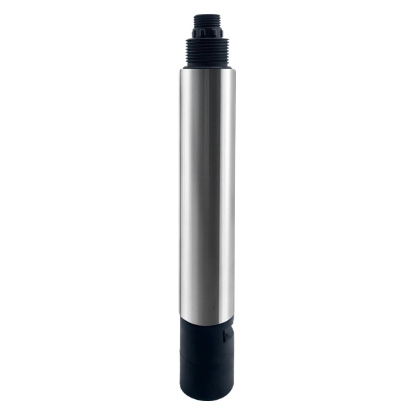
Monitoring Points for Oil Depot and Petrochemical Wastewater
| Location | Primary decision | Useful online evidence | Do not assume |
|---|---|---|---|
| Tank drainage or collection sump | Identify an oily batch before transfer | Oil-in-water trend, level, pH and conductivity | A bottom-mounted point will represent a floating free-oil layer. |
| Oil-water separator outlet | Detect carryover and separator upset | Oil-in-water trend plus flow and visual or sample confirmation | One universal threshold fits every product and detergent condition. |
| Equalization inlet | Warn the biological or chemical process of a shock load | Oil-in-water, COD trend, pH and conductivity | The alarm identifies the exact hydrocarbon or toxicity. |
| Treatment-stage outlet | Check removal trend and trigger investigation | Oil trend, COD trend, turbidity or TSS where relevant | Optical oil response equals a regulatory oil-and-grease method. |
| Final discharge or reuse point | Hold, investigate or confirm release condition | Validated online trend, flow state and paired reference sample | The online sensor replaces the approved compliance method without validation. |
This point-by-point design keeps each signal tied to an operational decision. It also prevents duplicate instruments from being installed at convenient but hydraulically weak locations.
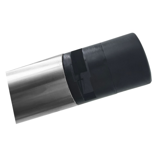
Verified YEX-S1PRO-OIL Selection Evidence
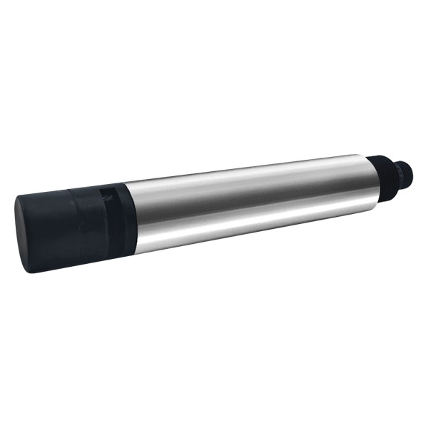
The current YEX-S1PRO-OIL manual lists narrow-band LED fluorescence for oil-in-water measurement, a 0-40.00 mg/L customizable range, 0.01 resolution, accuracy of ±3% of reading, a 30-second response time and automatic temperature compensation. It also lists 12-24 VDC power, RS485 Modbus, optional 4-20 mA, IP68 protection, a 316L stainless-steel plus ABS housing, a 5 m four-core shielded cable, immersion installation with a 3/4 NPT thread and optional self-cleaning. Operating conditions are listed as 0-50°C, non-freezing, and pressure below 0.2 MPa.
These are model specifications, not proof of recovery for every fuel, lubricant or wastewater matrix. The buyer should submit the likely oils, clean baseline, smallest actionable event, credible maximum, detergents, solids and interfering organics. The ordered range and alarm logic should then be confirmed in the quotation and site acceptance plan.
| Published item | YEX-S1PRO-OIL evidence | Selection action |
|---|---|---|
| Principle and range | Narrow-band LED fluorescence; 0-40.00 mg/L, customizable | Check actual oil response and choose a range that resolves the normal baseline and credible peak. |
| Accuracy and response | ±3% of reading; 0.01 resolution; 30-second response | Add transport, mixing, filtering and PLC persistence time to the total alarm response. |
| Output and power | RS485 Modbus; optional 4-20 mA; 12-24 VDC | Select the output at ordering and approve the register map or analog scaling. |
| Construction | 316L stainless steel plus ABS; IP68 | Review hydrocarbon, detergent, chemical, temperature and mechanical compatibility. |
| Installation and cleaning | Immersion, 3/4 NPT, 5 m shielded cable; optional self-cleaning | Specify bypass or tank arrangement, cable distance, drain, retrieval and cleaning-state handling. |
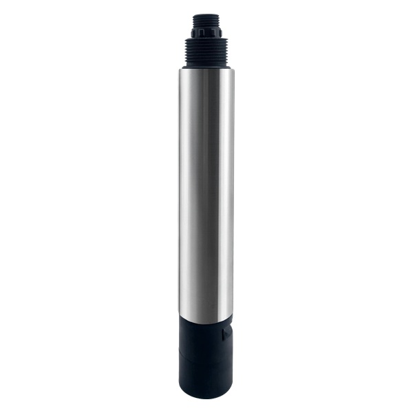
Use pH, Conductivity, COD and Solids as Supporting Evidence
An oil-in-water value answers a specific optical question. Add other parameters only when they support a defined treatment decision. pH can warn of an incompatible batch or treatment condition. Conductivity can identify a water-source or salt change. A UV254 COD sensor can provide a rapid organic-load trend, but color, turbidity and matrix changes require site correlation. Turbidity or TSS can help explain solids carryover, yet neither is a direct oil measurement.
For a separator and equalization system, the useful dashboard may combine oil trend, flow or pump state, tank level, pH, conductivity and retained-sample status. For a biological process, operators may also need COD trend, DO and solids information. Keep each parameter label, unit, quality flag and verification method explicit.
Installation and Sample Conditioning
Choose a continuously renewed and representative point. Avoid dead zones, settled sediment, trapped air, direct chemical injection and a location that sees only one vertical layer when the process can stratify. If free oil floats while emulsified oil remains distributed, the site survey must define which fraction and failure mode the online point is intended to detect.
A bypass can improve flow control, isolation, drainage and sample comparison, but the line adds transport delay and can collect deposits. Direct immersion can respond faster, but the probe still needs rigid positioning, cable protection and safe retrieval. Provide a sample valve close to the measuring point so an alarm can be checked without comparing different water or different times.
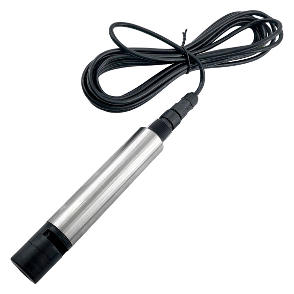
PLC, SCADA, Alarm Logic and Acceptance
For Modbus RS485, confirm address, baud rate, parity, register, data type, byte order, unit and the exact manual revision. The manual lists a default 9600 baud, no parity and floating-point CDAB data, but the commissioning team should verify the supplied device rather than copy settings from another model. The PLC must identify stale data, out-of-range values, maintenance mode and communication loss.
Build alarms from the clean operating baseline and representative event tests. A warning can request inspection and a same-point sample; a higher validated condition can trigger the approved hold, diversion or escalation. Use persistence or rate-of-change logic where bubbles, cleaning and hydraulic transitions create short spikes. Do not let an unvalidated single probe automatically stop or release a critical process.
FAT should verify the ordered model, range, output, cable, communication and documents. SAT should verify the installed point, oil response, clean-water recovery, reference sampling, alarm actions, communication-loss behavior and restart after power interruption.
Send Oil Depot Process Data for Sensor Selection
For this application, provide the information that changes oil-response, point selection and alarm design:
- Likely fuels, lubricants or process oils; clean-water baseline; smallest actionable event and credible maximum.
- Source map for tank drainage, runoff, separator, equalization, treatment outlet and final discharge.
- Detergents, suspended solids, color, COD trend, temperature, pH and conductivity conditions.
- Installation sketch, flow or tank conditions, sample tap, cleaning access, cable route and hazardous-area requirements.
- PLC or SCADA platform, selected output, alarm response, quantity, destination and acceptance method.
Review the YEX-S1PRO-OIL online oil-in-water sensor, then Send Your Project Requirements. The quotation should identify the exact model, ordered options, supplied documents and exclusions.
Oil Depot Wastewater Monitoring FAQ
Q1. What should an oil depot monitor first?
A1. Start with the failure path and operating action. Monitor the point where an oily batch can be detected before it reaches sensitive treatment, then add separator outlet and final-water checks when they support distinct actions.
Q2. Can an oil-in-water sensor detect every petroleum product?
A2. No. Fluorescence response depends on the actual oil and wastewater matrix. Submit the likely products and use representative testing before the sensor is accepted for alarm duty.
Q3. Can online oil data replace an oil-and-grease laboratory result?
A3. Not automatically. Use the approved laboratory method for compliance or identification, and document any site correlation before presenting an optical online value as equivalent evidence.
Q4. Where should the sensor be installed after an oil-water separator?
A4. Use a well-mixed outlet or controlled bypass that receives separator carryover, with stable flow, isolation, drain, cleaning access and a same-point confirmation sample valve.
Q5. Why combine oil monitoring with COD, pH or conductivity?
A5. These parameters help identify a broader wastewater change and its treatment impact. They do not replace the oil measurement, and each needs its own method and alarm purpose.
Q6. How should an oil alarm be set?
A6. Record the clean baseline and representative oil-response data, then define warning, sustained action and reset rules. Include persistence, sample confirmation and a named operator response.
Q7. Does YEX-S1PRO-OIL support PLC and SCADA?
A7. The current manual lists RS485 Modbus and optional 4-20 mA. Select the output at ordering and verify address, register, unit, scaling, fault and maintenance behavior during FAT and SAT.
Q8. Is automatic cleaning enough for oily wastewater?
A8. No. Optional self-cleaning can reduce deposits, but inspection, manual cleaning, reference checks and cleaning-state records remain necessary. Cleaning frequency should follow actual fouling evidence.
Q9. What should be included in the quotation?
A9. Include the exact model, range, output, cable, mounting, cleaning option, supplied documents, spares, FAT, delivery scope and exclusions, plus the agreed site validation and acceptance method.
Q10. What information speeds up model selection?
A10. Provide oil types, normal and peak values, water matrix, process locations, installation drawing, PLC or SCADA interface, alarm action, quantity, destination and required documents.
Summary
A reliable oil depot wastewater monitoring system separates oil-event warning, treatment protection and final-water verification. Use a validated oil-in-water response at representative points, add pH, conductivity, COD or solids only when they support a defined decision, and expose data quality in PLC or SCADA. Confirm the YEX-S1PRO-OIL range, output, installation and material boundary from the current manual, then include actual oils, sample access, alarm actions and acceptance evidence in the project quotation.



